| Last Modified: 08-28-2024 | 6.11:8.1.0 | Doc ID: RM100000000VJLM |
| Model Year Start: 2016 | Model: Sienna | Prod Date Range: [12/2015 - ] |
| Title: THEFT DETERRENT / KEYLESS ENTRY: ENGINE IMMOBILISER SYSTEM(w/ Smart Key System): Security Indicator Light Circuit; 2016 - 2020 MY Sienna [12/2015 - ] | ||
|
Security Indicator Light Circuit |
DESCRIPTION
The security indicator light blinks continuously due to a continuous signal received from the certification ECU while the engine immobiliser is set.
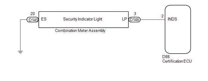
WIRING DIAGRAM
CAUTION / NOTICE / HINT
NOTICE:
If the certification ECU is replaced, register the key and ECU communication ID (See page
![2016 MY Sienna [12/2015 - 08/2016]; THEFT DETERRENT / KEYLESS ENTRY: ENGINE IMMOBILISER SYSTEM(w/ Smart Key System): REGISTRATION](/t3Portal/stylegraphics/info.gif) ).
).
PROCEDURE
|
1. |
PERFORM ACTIVE TEST USING TECHSTREAM (SECURITY INDICATOR) |
(a) Connect the Techstream to the DLC3.
(b) Turn the engine switch on (IG).
(c) Turn the Techstream on.
(d) Enter the following menus: Body Electrical / Smart Key / Active Test.
(e) Perform the Active Test according to the display on the Techstream.
Smart Key
|
Tester Display |
Test Part |
Control Range |
Diagnostic Note |
|---|---|---|---|
|
Security Indicator |
Security indicator light |
ON or OFF |
- |
OK:
The security indicator light turns on and off according to operation via the Techstream.
| OK |

|
REPLACE CERTIFICATION ECU (See page
|
|

|
2. |
CHECK HARNESS AND CONNECTOR (CERTIFICATION ECU - COMBINATION METER ASSEMBLY) |
(a) Disconnect the certification ECU connector.
(b) Disconnect the combination meter assembly connector.
(c) Measure the resistance according to the value(s) in the table below.
Standard Resistance:
|
Tester Connection |
Condition |
Specified Condition |
|---|---|---|
|
D88-2 (INDS) - D146-3 (LP) |
Always |
Below 1 Ω |
|
D88-2 (INDS) - Body ground |
Always |
10 kΩ or higher |
|
D146-3 (LP) - Body ground |
Always |
10 kΩ or higher |
| NG |
|
REPAIR OR REPLACE HARNESS OR CONNECTOR |
|
|
3. |
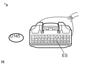
CHECK HARNESS AND CONNECTOR (COMBINATION METER ASSEMBLY - BODY GROUND) |
|
(a) Measure the resistance according to the value(s) in the table below. Standard Resistance:
Text in Illustration
|
|
| OK |
|
| NG |
|
REPAIR OR REPLACE HARNESS OR CONNECTOR |
|
|
|