- Engine switch off
- 30 seconds after door opened and closed
- Brake pedal not depressed
| Last Modified: 08-28-2024 | 6.11:8.1.0 | Doc ID: RM100000000VJLJ |
| Model Year Start: 2016 | Model: Sienna | Prod Date Range: [12/2015 - 08/2016] |
| Title: THEFT DETERRENT / KEYLESS ENTRY: ENGINE IMMOBILISER SYSTEM(w/ Smart Key System): TERMINALS OF ECU; 2016 MY Sienna [12/2015 - 08/2016] | ||
TERMINALS OF ECU
1. CHECK ENGINE SWITCH
(a) Disconnect the D33 engine switch connector.

(b) Measure the resistance according to the value(s) in the table below.
HINT:
Measure the values on the wire harness side with the connector disconnected.
|
Terminal No. (Symbol) |
Wiring Color |
Terminal Description |
Condition |
Specified Condition |
|---|---|---|---|---|
|
D33-8 (AGND) - Body ground |
R - Body ground |
Ground |
Always |
Below 1 Ω |
If the result is not as specified, there may be a malfunction in the wire harness.
(c) Reconnect the D33 engine switch connector.
(d) Measure the voltage according to the value(s) in the table below.
|
Terminal No. (Symbol) |
Wiring Color |
Terminal Description |
Condition |
Specified Condition |
|---|---|---|---|---|
|
D33-9 (TXCT) - D33-8 (AGND) |
V - R |
Key code output signal |
|
Below 1 V |
|
D33-9 (TXCT) - D33-8 (AGND) |
V - R |
Key code output signal |
|
Pulse generation (See waveform 1) |
|
D33-10 (CODE) - D33-8 (AGND) |
L - R |
Demodulated signal of key code data |
|
Below 1 V |
|
D33-10 (CODE) - D33-8 (AGND) |
L - R |
Demodulated signal of key code data |
|
Pulse generation (See waveform 2) |
|
D33-14 (VC5) - D33-8 (AGND) |
G - R |
Power supply |
|
Below 1 V |
|
D33-14 (VC5) - D33-8 (AGND) |
G - R |
Power supply |
|
Pulse generation (See waveform 3) |
If the result is not as specified, the engine switch may have a malfunction.
(e) Inspect using an oscilloscope.
(1) Waveform 1
|
Item |
Content |
|---|---|
|
Tester Connection |
D33-9 (TXCT) - D33-8 (AGND) |
|
Tool Setting |
2 V/DIV., 50 ms./DIV. |
|
Condition |
|
(2) Waveform 2
|
Item |
Content |
|---|---|
|
Tester Connection |
D33-10 (CODE) - D33-8 (AGND) |
|
Tool Setting |
2 V/DIV., 50 ms./DIV. |
|
Condition |
|
(3) Waveform 3
|
Item |
Content |
|---|---|
|
Tester Connection |
D33-14 (VC5) - D33-8 (AGND) |
|
Tool Setting |
2 V/DIV., 200 ms./DIV. |
|
Condition |
|
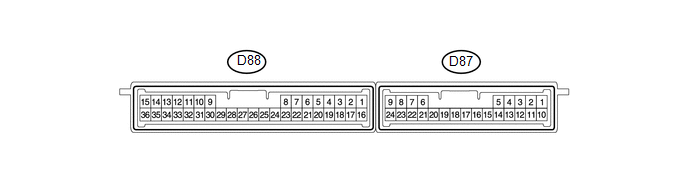
2. CHECK CERTIFICATION ECU
(a) Disconnect the D88 certification ECU connector.
(b) Measure the resistance and voltage according to the value(s) in the table below.
HINT:
Measure the values on the wire harness side with the connector disconnected.
|
Terminal No. (Symbol) |
Wiring Color |
Terminal Description |
Condition |
Specified Condition |
|---|---|---|---|---|
|
D88-1 (+B) - D88-15 (E) |
G - W-B |
+B power supply |
Always |
11 to 14 V |
|
D88-15 (E) - Body ground |
W-B - Body ground |
Ground |
Always |
Below 1 Ω |
If the result is not as specified, there may be a malfunction in the wire harness.
(c) Reconnect the D88 certification ECU connector.
(d) Measure the resistance and voltage according to the value(s) in the table below.
|
Terminal No. (Symbol) |
Wiring Color |
Terminal Description |
Condition |
Specified Condition |
|---|---|---|---|---|
|
D88-2 (INDS) - Body ground |
B - Body ground |
Security indicator light signal |
Engine switch on (IG), security indicator light off |
Below 2 V |
|
D88-2 (INDS) - Body ground |
B - Body ground |
Security indicator light signal |
Engine switch off, security indicator light blinks |
Pulse generation |
|
D88-12 (TXCT) - D88-36 (AGND) |
V - R |
Engine switch TXCT output |
|
Below 1 V |
|
D88-12 (TXCT) - D88-36 (AGND) |
V - R |
Engine switch TXCT output |
|
Pulse generation (See waveform 1) |
|
D88-13 (CODE) - D88-36 (AGND) |
L - R |
Engine switch CODE input |
|
Below 1 V |
|
D88-13 (CODE) - D88-36 (AGND) |
L - R |
Engine switch CODE input |
|
Pulse generation (See waveform 2) |
|
D88-16 (IG) - D88-15 (E) |
B - W-B |
Ignition power supply |
Engine switch off |
Below 1 V |
|
D88-16 (IG) - D88-15 (E) |
B - W-B |
Ignition power supply |
Engine switch on (IG) |
11 to 14 V |
|
D88-28 (VC5) - D88-36 (AGND) |
G - R |
Engine switch power supply |
|
Below 1 V |
|
D88-28 (VC5) - D88-36 (AGND) |
G - R |
Engine switch power supply |
|
Pulse generation (See waveform 3) |
|
D88-34 (EFII) - D88-15 (E) |
G - W-B |
ECM input signal |
Engine switch off |
11 to 14 V |
|
D88-34 (EFII) - D88-15 (E) |
G - W-B |
ECM input signal |
Within 3 seconds after the starter operates and initial combustion occurs, or within 3 seconds after engine switch first turned on (IG) after battery disconnected and connected |
Pulse generation (See waveform 4) |
|
D88-35 (EFIO) - D88-15 (E) |
V - W-B |
ECM output signal |
Engine switch off |
11 to 14 V |
|
D88-35 (EFIO) - D88-15 (E) |
V - W-B |
ECM output signal |
Engine switch on (IG) |
Pulse generation (See waveform 5) |
|
D88-36 (AGND) - Body ground |
R - Body ground |
Engine switch ground |
Always |
Below 1 Ω |
If the result is not as specified, the certification ECU may have a malfunction.
(e) Inspect using an oscilloscope.
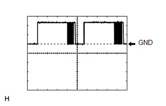
(1) Waveform 1
|
Item |
Content |
|---|---|
|
Tester Connection |
D88-12 (TXCT) - D88-36 (AGND) |
|
Tool Setting |
2 V/DIV., 50 ms./DIV. |
|
Condition |
|
(2) Waveform 2
|
Item |
Content |
|---|---|
|
Tester Connection |
D88-13 (CODE) - D88-36 (AGND) |
|
Tool Setting |
2 V/DIV., 50 ms./DIV. |
|
Condition |
|
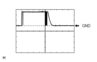
(3) Waveform 3
|
Item |
Content |
|---|---|
|
Tester Connection |
D88-28 (VC5) - D88-36 (AGND) |
|
Tool Setting |
2 V/DIV., 200 ms./DIV. |
|
Condition |
|
(4) Waveform 4
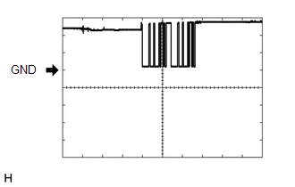
|
Item |
Content |
|---|---|
|
Tester Connection |
D88-34 (EFII) - D88-15 (E) |
|
Tool Setting |
5 V/DIV., 500 ms/DIV. |
|
Condition |
Within 3 seconds after the starter operates and initial combustion occurs, or within 3 seconds after engine switch first turned on (IG) after battery disconnected and connected |
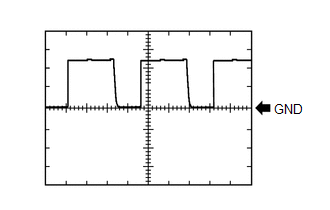
(5) Waveform 5
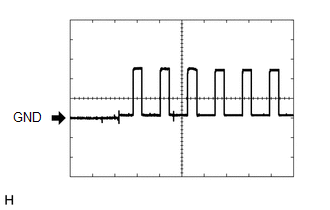
|
Item |
Content |
|---|---|
|
Tester Connection |
D88-35 (EFIO) - D88-15 (E) |
|
Tool Setting |
5 V/DIV., 50 ms./DIV. |
|
Condition |
Engine switch on (IG) |
3. CHECK STEERING LOCK ECU
(a) Disconnect the D29 steering lock ECU connector.

(b) Measure the resistance and voltage according to the value(s) in the table below.
HINT:
Measure the values on the wire harness side with the connector disconnected.
|
Terminal No. (Symbol) |
Wiring Color |
Terminal Description |
Condition |
Specified Condition |
|---|---|---|---|---|
|
D29-1 (GND) - Body ground |
W-B - Body ground |
Ground |
Always |
Below 1 Ω |
|
D29-6 (IG2) - Body ground |
B - Body ground |
Ignition power supply |
Engine switch off |
Below 1 V |
|
D29-6 (IG2) - Body ground |
B - Body ground |
Ignition power supply |
Engine switch on (IG) |
11 to 14 V |
|
D29-7 (B) - Body ground |
R - Body ground |
+B power supply |
Always |
11 to 14 V |
If the result is not as specified, there may be a malfunction in the wire harness.
4. CHECK ECM
(a) The values listed under "Specified Condition" are reference values. Because waterproof connectors are used for ECM, inspections can not be performed with the connectors connected.
|
Terminal No. (Symbol) |
Wiring Color |
Terminal Description |
Condition |
Specified Condition |
|---|---|---|---|---|
|
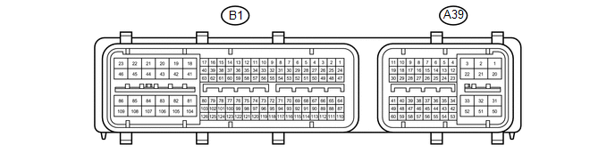
B1-81 (E1) - Body ground |
BR - Body ground |
Ground |
Always |
Below 1 Ω |
|
A39-29 (IMO) - B1-81 (E1) |
G - BR |
Certification ECU output signal |
Engine switch off |
11 to 14 V |
|
A39-29 (IMO) - B1-81 (E1) |
G - BR |
Certification ECU output signal |
Within 3 seconds after the starter operates and initial combustion occurs, or within 3 seconds after engine switch first turned on (IG) after battery disconnected and connected |
Pulse generation (See waveform 1) |
|
A39-40 (IMI) - B1-81 (E1) |
V - BR |
Certification ECU input signal |
Engine switch off |
11 to 14 V |
|
A39-40 (IMI) - B1-81 (E1) |
V - BR |
Certification ECU input signal |
Engine switch on (IG) |
Pulse generation (See waveform 2) |
(b) Waveform:
(1) Waveform 1
|
Item |
Content |
|---|---|
|
Tester Connection |
A39-29 (IMO) - B1-81 (E1) |
|
Tool Setting |
5 V/DIV., 500 ms./DIV. |
|
Condition |
Within 3 seconds after the starter operates and initial combustion occurs, or within 3 seconds after engine switch first turned on (IG) after battery disconnected and connected |
(2) Waveform 2
|
Item |
Content |
|---|---|
|
Tester Connection |
A39-40 (IMI) - B1-81 (E1) |
|
Tool Setting |
5 V/DIV., 50 ms./DIV. |
|
Condition |
Engine switch on (IG) |
5. CHECK POWER MANAGEMENT CONTROL ECU
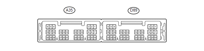
(a) Disconnect the D89 power management control ECU connector.
(b) Measure the resistance and voltage according to the value(s) in the table below.
HINT:
Measure the values on the wire harness side with the connector disconnected.
|
Terminal No. (Symbol) |
Wiring Color |
Terminal Description |
Condition |
Specified Condition |
|---|---|---|---|---|
|
D89-1 (AM22) - Body ground |
R - Body ground |
Battery |
Always |
11 to 14 V |
|
D89-2 (AM21) - Body ground |
R - Body ground |
Battery |
Always |
11 to 14 V |
|
D89-5 (GND2) - Body ground |
W-B - Body ground |
Ground |
Always |
Below 1 Ω |
|
D89-6 (GND) - Body ground |
W-B - Body ground |
Ground |
Always |
Below 1 Ω |
If the result is not as specified, there may be a malfunction in the wire harness.
6. COMBINATION METER ASSEMBLY
(a) Disconnect the D145 combination meter assembly connector.
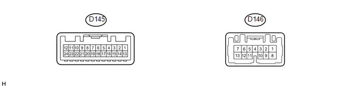
(b) Measure the voltage and resistance according to the value(s) in the table below.
HINT:
Measure the values on the wire harness side with the connector disconnected.
|
Terminal No. (Symbol) |
Wiring Color |
Terminal Description |
Condition |
Specified Condition |
|---|---|---|---|---|
|
D145-1 (B) - Body ground |
W - Body ground |
Battery |
Always |
11 to 14 V |
|
D145-20 (ES) - Body ground |
BR - Body ground |
Ground |
Always |
Below 1 Ω |
If the result is not as specified, there may be a malfunction in the wire harness.
(c) Reconnect the D145 combination meter assembly connector.
(d) Measure the voltage and resistance according to the value(s) in the table below.
|
Terminal No. (Symbol) |
Wiring Color |
Terminal Description |
Condition |
Specified Condition |
|---|---|---|---|---|
|
D146-3 (LP) - Body ground |
B - Body ground |
Security indicator light signal |
Engine switch on (IG), security indicator light off |
Below 2 V |
|
D146-3 (LP) - Body ground |
B - Body ground |
Security indicator light signal |
Engine switch off, security indicator light blinks |
Pulse generation |
If the result is not as specified, the combination meter assembly may have a malfunction.
|
|
|