| Last Modified: 08-28-2024 | 6.11:8.1.0 | Doc ID: RM100000000VJL8 |
| Model Year Start: 2016 | Model: Sienna | Prod Date Range: [12/2015 - ] |
| Title: THEFT DETERRENT / KEYLESS ENTRY: ENGINE IMMOBILISER SYSTEM(w/o Smart Key System): Security Indicator Light Does not Blink; 2016 - 2020 MY Sienna [12/2015 - ] | ||
|
Security Indicator Light Does not Blink |
DESCRIPTION
- When the engine immobiliser system is set, the security indicator light blinks continuously, but does not illuminate if the engine immobiliser system is not set.
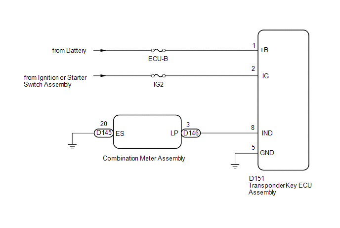
WIRING DIAGRAM
CAUTION / NOTICE / HINT
NOTICE:
- Inspect the fuses for circuits related to this system before performing the following inspection procedure.
-
When replacing the transponder key ECU assembly, refer to Registration (See page
![2016 - 2020 MY Sienna [12/2015 - ]; THEFT DETERRENT / KEYLESS ENTRY: ENGINE IMMOBILISER SYSTEM(w/o Smart Key System): REGISTRATION](/t3Portal/stylegraphics/info.gif) ).
).
PROCEDURE
|
1. |
CHECK FOR DTC |
(a) Check for DTCs (See page
).
OK:
DTC is not output.
| NG |

|
GO TO DIAGNOSTIC TROUBLE CODE CHART (See page
|
|

|
2. |
PERFORM ACTIVE TEST USING TECHSTREAM (SECURITY INDICATOR) |
(a) Check that the security indicator light illuminates when operating it with the Active Test (See page
).
Immobiliser
|
Tester Display |
Test Part |
Control Range |
Diagnostic Note |
|---|---|---|---|
|
Security Indicator |
Security indicator light |
ON/OFF |
- |
OK:
Security indicator light can be turned on and off using the Techstream.
| NG |
|
|
|
3. |
READ VALUE USING TECHSTREAM (IMMOBILISER) |
(a) Turn the ignition switch off.
HINT:
When using the Techstream with the ignition switch off to troubleshoot: Connect the Techstream to the DLC3 and turn a courtesy light switch on and off at intervals of 1.5 seconds until communication between the Techstream and vehicle begins.
(b) Using the Techstream, read the Data List (See page
).
Immobiliser
|
Tester Display |
Measurement Item/Range |
Normal Condition |
Diagnostic Note |
|---|---|---|---|
|
Immobiliser |
Engine immobiliser system status/SET or UNSET |
UNSET: Ignition switch ON SET: Without key |
- |
| OK |
|
| NG |
|
|
4. |
CHECK HARNESS AND CONNECTOR (TRANSPONDER KEY ECU ASSEMBLY - COMBINATION METER ASSEMBLY AND BODY GROUND) |
(a) Disconnect the D151 transponder key ECU assembly connector.
(b) Disconnect the D145 or D146 combination meter assembly connectors.
(c) Measure the resistance according to the value(s) in the table below.
Standard Resistance:
|
Tester Connection |
Condition |
Specified Condition |
|---|---|---|
|
D151-8 (IND) - D146-3 (LP) |
Always |
Below 1 Ω |
|
D145-20 (ES) - Body ground |
Always |
Below 1 Ω |
|
D151-8 (IND) or D146-3 (LP) - Body ground |
Always |
10 kΩ or higher |
| NG |
|
REPAIR OR REPLACE HARNESS OR CONNECTOR |
|
|
5. |
REPLACE COMBINATION METER ASSEMBLY |
(a) Temporarily replace the combination meter assembly with a new one or known good one (See page
).
(b) When the immobiliser is set, check that the security indicator light blinks.
OK:
Security indicator light blinks.
| OK |
|
END (COMBINATION METER ASSEMBLY WAS DEFECTIVE) |
| NG |
|
|
6. |
CHECK HARNESS AND CONNECTOR (TRANSPONDER KEY ECU ASSEMBLY - BATTERY AND BODY GROUND) |
|
(a) Disconnect the transponder key ECU assembly connector. |
|
(b) Measure the resistance according to the value(s) in the table below.
Standard Resistance:
|
Tester Connection |
Condition |
Specified Condition |
|---|---|---|
|
D151-5 (GND) - Body ground |
Always |
Below 1 Ω |
(c) Measure the voltage according to the value(s) in the table below.
Standard Voltage:
|
Tester Connection |
Switch Condition |
Specified Condition |
|---|---|---|
|
D151-1 (+B) - Body ground |
Always |
11 to 14 V |
|
D151-2 (IG) - Body ground |
Ignition switch off |
Below 1 V |
|
Ignition switch ON |
11 to 14 V |
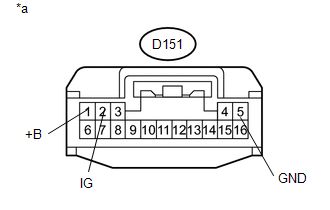
Text in Illustration
|
*a |
Front view of wire harness connector (to Transponder Key ECU Assembly) |
| OK |
|
| NG |
|
REPAIR OR REPLACE HARNESS OR CONNECTOR |
|
|
|