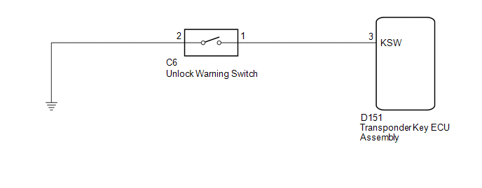
- Wire harness or connector
- Unlock warning switch
- Transponder key ECU
| Last Modified: 08-28-2024 | 6.11:8.1.0 | Doc ID: RM100000000VJKZ |
| Model Year Start: 2016 | Model: Sienna | Prod Date Range: [12/2015 - ] |
| Title: THEFT DETERRENT / KEYLESS ENTRY: ENGINE IMMOBILISER SYSTEM(w/o Smart Key System): B2780; Push Switch / Key Unlock Warning Switch Malfunction; 2016 - 2020 MY Sienna [12/2015 - ] | ||
|
DTC |
B2780 |
Push Switch / Key Unlock Warning Switch Malfunction |
DESCRIPTION
This DTC is stored if the transponder key ECU does not detect that the unlock warning switch is ON even when the ignition switch is ON. Under normal conditions, the unlock warning switch is ON when the ignition switch is ON.
|
DTC No. |
DTC Detection Condition |
Trouble Area |
|---|---|---|
|
B2780 |
"Unlock warning switch ON" is not detected when the ignition switch is ON. |
|
WIRING DIAGRAM

CAUTION / NOTICE / HINT
NOTICE:
If the transponder key ECU is replaced, register the key and ECU communication ID (See page
![2016 - 2020 MY Sienna [12/2015 - ]; THEFT DETERRENT / KEYLESS ENTRY: ENGINE IMMOBILISER SYSTEM(w/o Smart Key System): REGISTRATION](/t3Portal/stylegraphics/info.gif) ).
).
PROCEDURE
|
1. |
READ VALUE USING TECHSTREAM (KEY SW) |
(a) Connect the Techstream to the DLC3.
(b) Turn the ignition switch to ON.
(c) Turn the Techstream on.
(d) Enter the following menus: Body Electrical / Immobiliser / Data List.
(e) Read the Data List according to the display on the Techstream.
Immobiliser
|
Tester Display |
Measurement Item/Range |
Normal Condition |
Diagnostic Note |
|---|---|---|---|
|
Key SW |
Unlock warning switch signal/ON or OFF |
ON: Key in ignition key cylinder OFF: No key in ignition key cylinder |
- |
OK:
On the Techstream screen, the item changes between ON and OFF according to the chart above.
| OK |

|
|
|
2. |
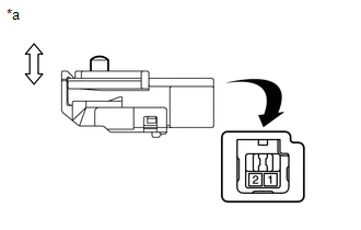
INSPECT UNLOCK WARNING SWITCH |
|
(b) Measure the resistance according to the value(s) in the table below.
Standard Resistance:
|
Tester Connection |
Switch Condition |
Specified Condition |
|---|---|---|
|
1 - 2 |
Switch pushed (Key set) |
Below 1 Ω |
|
1 - 2 |
Switch free (Key removed) |
10 kΩ or higher |
Text in Illustration
|
*a |
Component without harness connected (Unlock Warning Switch) |
| NG |

|
|
|
3. |
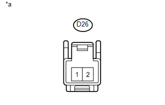
CHECK HARNESS AND CONNECTOR (UNLOCK WARNING SWITCH - BODY GROUND) |
|
(a) Measure the resistance according to the value(s) in the table below. Standard Resistance:
Text in Illustration
|
|
| NG |

|
REPAIR OR REPLACE HARNESS OR CONNECTOR |
|
|
4. |
CHECK HARNESS AND CONNECTOR (TRANSPONDER KEY ECU - UNLOCK WARNING SWITCH) |
(a) Disconnect the transponder key ECU connector.
(b) Measure the resistance according to the value(s) in the table below.
Standard Resistance:
|
Tester Connection |
Condition |
Specified Condition |
|---|---|---|
|
D151-3 (KSW) - D26-1 |
Always |
Below 1 Ω |
|
D151-3 (KSW) - Body ground |
Always |
10 kΩ or higher |
|
D26-1 - Body ground |
Always |
10 kΩ or higher |
| OK |

|
| NG |

|
REPAIR OR REPLACE HARNESS OR CONNECTOR |
|
|
|


