| Last Modified: 08-28-2024 | 6.11:8.1.0 | Doc ID: RM100000000VJKQ |
| Model Year Start: 2016 | Model: Sienna | Prod Date Range: [12/2015 - ] |
| Title: THEFT DETERRENT / KEYLESS ENTRY: SMART KEY SYSTEM(for Entry Function): Power Slide Door Entry Function does not Operate; 2016 - 2020 MY Sienna [12/2015 - ] | ||
|
Power Slide Door Entry Function does not Operate |
DESCRIPTION
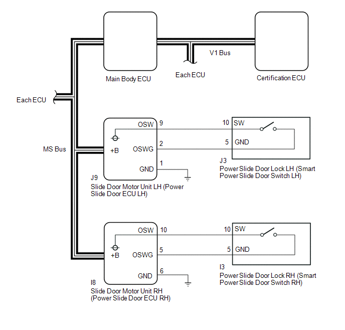
Pulling on the rear outside door handle for approximately 1 second causes the power slide door ECU to send a smart power slide door request signal to the certification ECU via the main body ECU. Once the certification ECU judges and certifies the key ID code, the certification ECU outputs a smart power slide door request signal to the main body ECU. The main body ECU then unlocks the doors and simultaneously transmits a power slide door open request signal to the power slide door ECU, which then performs a slide door open operation.
FAIL-SAFE
If the door unlock operation has completed but the power slide door open operation does not successfully complete (for example, if the door is covered by ice and is frozen shut), then the doors automatically lock after 30 seconds.
WIRING DIAGRAM
CAUTION / NOTICE / HINT
NOTICE:
-
The smart key system (for Entry Function) uses a multiplex communication system (LIN communication system) and the CAN communication system. Inspect the communication function by following How to Proceed with Troubleshooting (See page
![2016 - 2020 MY Sienna [12/2015 - ]; THEFT DETERRENT / KEYLESS ENTRY: SMART KEY SYSTEM(for Entry Function): HOW TO PROCEED WITH TROUBLESHOOTING](/t3Portal/stylegraphics/info.gif) ). Troubleshoot the smart key system (for Entry Function) after confirming that the communication systems are functioning properly.
). Troubleshoot the smart key system (for Entry Function) after confirming that the communication systems are functioning properly.
- When using the Techstream with the engine switch off to troubleshoot: Connect the Techstream to the DLC3 and turn a courtesy light switch on and off at 1.5-second intervals until communication between the Techstream and vehicle begins.
PROCEDURE
|
1. |
READ VALUE USING TECHSTREAM (OUTSIDE PSD SWITCH OPERATION) |
(a) Connect the Techstream to the DLC3.
(b) Turn the power switch on (IG).
(c) Turn the Techstream on.
(d) Enter the following menus: Body Electrical / RR Door or RL Door / Utility / Customize.
(e) Select the setting by referring to the table below.
RR Door or RL Door
|
Display (item) |
Default |
Function |
Setting |
|---|---|---|---|
|
Outside PSD SW Operation |
ON |
Function to change the operation method of operating the smart power slide door. |
ON or OFF |
|
Result |
Proceed to |
|---|---|
|
Customize setting is ON |
A |
|
Customize setting is off |
B |
| B |

|
|

|
2. |
READ VALUE USING TECHSTREAM (OUTSIDE PSD SWITCH) |
(a) Connect the Techstream to the DLC3.
(b) Turn the power switch on (IG).
(c) Turn the Techstream on.
(d) Enter the following menus: Body Electrical / RR Door or RL Door / Data List.
(e) Read the Data List according to the display on the Techstream.
RR Door or RL Door
|
Tester Display |
Measurement Item/Range |
Normal Condition |
Diagnostic Note |
|---|---|---|---|
|
Outside PSD Switch |
Smart power slide door switch signal/ON or OFF |
ON: Rear door outside handle pulled for 0.2 seconds or more OFF: Rear door outside handle not pulled |
- |
OK:
The Techstream indicates ON and OFF according to the rear door outside handle operation shown in the table.
| OK |
|
|
|
3. |
CHECK HARNESS AND CONNECTOR (POWER SLIDE DOOR ECU POWER SOURCE AND GROUND) |
|
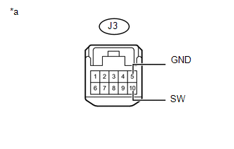
(a) for LH Side (1) Disconnect the J3 slide door lock LH connector. (2) Measure the voltage and resistance according to the values in the table below. Standard:
Text in Illustration
|
|
|
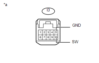
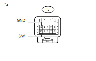
(b) for RH Side (1) Disconnect the I3 slide door lock RH connector. (2) Measure the voltage and resistance according to the values in the table below. Standard:
Text in Illustration
|
|
| NG |
|
|
|
4. |
INSPECT POWER SLIDE DOOR LOCK ASSEMBLY (SMART POWER SLIDE DOOR SWITCH) |
|
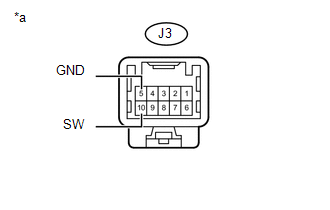
(a) for LH Side (1) Remove the power slide door lock LH (See page
(2) Measure the resistance according to the value(s) in the table below. Standard Resistance:
Text in Illustration
|
|
|
(b) for RH Side (1) Remove the power slide door lock RH (See page
(2) Measure the resistance according to the value(s) in the table below. Standard Resistance:
Text in Illustration
|
|
| OK |
|
REPLACE SLIDE DOOR MOTOR UNIT (POWER SLIDE DOOR ECU) (See page
|
| NG |
|
REPLACE POWER SLIDE DOOR LOCK ASSEMBLY (SMART POWER SLIDE DOOR SWITCH) (See page
|
|
5. |
CHECK HARNESS AND CONNECTOR (POWER SLIDE DOOR ECU - SMART POWER SLIDE DOOR SWITCH AND GROUND) |
(a) for LH Side
(1) Disconnect the J9 power slide door ECU connector.
(2) Measure the resistance according to the values in the table below.
Standard Resistance:
|
Tester Connection |
Condition |
Specified Condition |
|---|---|---|
|
J9-9 (OSW) - J3-10 (SW) |
Always |
Below 1 Ω |
|
J9-2 (OSWG) - J3-5 (GND) |
Always |
Below 1 Ω |
|
J9-1(GND) - Body ground |
Always |
Below 1 Ω |
(b) for RH Side
(1) Disconnect the I8 power slide door ECU connector.
(2) Measure the resistance according to the values in the table below.
Standard Resistance:
|
Tester Connection |
Condition |
Specified Condition |
|---|---|---|
|
I8-10 (OSW) - I3-10 (SW) |
Always |
Below 1 Ω |
|
I8-5 (OSWG) - I3-5 (GND) |
Always |
Below 1 Ω |
|
I8-6(GND) - Body ground |
Always |
Below 1 Ω |
| OK |
|
REPLACE SLIDE DOOR MOTOR UNIT (POWER SLIDE DOOR ECU) (See page
|
| NG |
|
REPAIR OR REPLACE HARNESS OR CONNECTOR |
|
|
|