| Last Modified: 08-28-2024 | 6.11:8.1.0 | Doc ID: RM100000000VJKG |
| Model Year Start: 2016 | Model: Sienna | Prod Date Range: [12/2015 - ] |
| Title: THEFT DETERRENT / KEYLESS ENTRY: SMART KEY SYSTEM(for Entry Function): Back Door Entry Lock and Unlock Functions do not Operate; 2016 - 2020 MY Sienna [12/2015 - ] | ||
|
Back Door Entry Lock and Unlock Functions do not Operate |
DESCRIPTION
When the back door entry lock and unlock functions do not operate, one of the following may be malfunctioning: 1) power door lock control system; 2) outside electrical key oscillator (for rear side); 3) certification ECU (smart key ECU assembly), or 4) back door opener switch assembly.
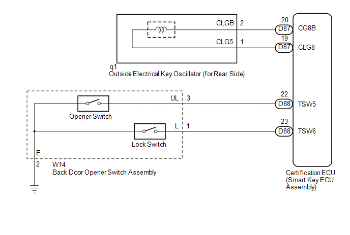
WIRING DIAGRAM
CAUTION / NOTICE / HINT
NOTICE:
-
The smart key system (for entry function) uses a multiplex communication system (LIN communication system) and CAN communication system. Inspect the communication function by following How to Proceed with Troubleshooting (See page
![2016 - 2020 MY Sienna [12/2015 - ]; THEFT DETERRENT / KEYLESS ENTRY: SMART KEY SYSTEM(for Entry Function): HOW TO PROCEED WITH TROUBLESHOOTING](/t3Portal/stylegraphics/info.gif) ). Troubleshoot the smart key system (for entry function) after confirming that the communication system is functioning properly.
). Troubleshoot the smart key system (for entry function) after confirming that the communication system is functioning properly.
- Confirm that another key is not in the cabin.
PROCEDURE
|
1. |
CHECK POWER DOOR LOCK OPERATION |
(a) When the door control switch on the master switch assembly is operated, check that the doors unlock and lock according to switch operation (See page
).
OK:
Door locks operate normally.
| NG |

|
GO TO POWER DOOR LOCK CONTROL SYSTEM (Proceed to Problem Symptoms Table) |
|

|
2. |
READ VALUE USING TECHSTREAM |
(a) Connect the Techstream to the DLC3.
(b) Turn the engine switch on (IG).
(c) Turn the Techstream on.
(d) Enter the following menus: Body Electrical / Smart Key / Data List.
(e) Read the Data List according to the display on the Techstream.
Smart Key (Certification ECU (Smart Key ECU Assembly))
|
Tester Display |
Measurement Item/Display |
Normal Condition |
Diagnostic Note |
|---|---|---|---|
|
Tr/B-Door Lock SW |
Back door opener switch assembly (lock switch) / ON or OFF |
ON: Back door opener switch assembly (lock switch) pushed OFF: Back door opener switch assembly (lock switch) not pushed |
- |
|
Tr/B-Door Unlock SW |
Back door opener switch assembly (opener switch) / ON or OFF |
ON: Back door opener switch assembly (opener switch) pushed OFF: Back door opener switch assembly (opener switch) not pushed |
- |
OK:
On the Techstream screen, the display changes between ON and OFF as shown in the chart above.
| NG |
|
|
|
3. |
CHECK WAVE ENVIRONMENT |
|
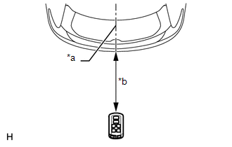
(a) Bring the key near the outside electrical key oscillator (for rear side), and perform an entry back door open and entry lock functions check. Text in Illustration
NOTICE: If the key is brought within 0.2 m (0.656 ft.) of the rear bumper, communication is not possible. HINT:
OK: Entry functions operate normally. |
|
| OK |
|
AFFECTED BY WAVE INTERFERENCE |
|
|
4. |
PERFORM KEY DIAGNOSTIC MODE INSPECTION |
|
(a) Diagnostic mode inspection (outside electrical key oscillator (for rear side)) Text in Illustration
(1) Connect the Techstream to the DLC3. (2) Turn the engine switch on (IG). (3) Turn the Techstream on. (4) Enter the following menus: Body Electrical / Smart Key / Key Communication Check / Overhead + Back Door. (5) When the key is held at the same height as the rear bumper upper surface and aligned with the center of the rear of the vehicle, check that the wireless door lock buzzer sounds. HINT: If the buzzer sounds, it can be determined that the outside electrical key oscillator (for rear side) is operating normally. OK: Wireless door lock buzzer sounds. |
|
| OK |
|
REPLACE CERTIFICATION ECU (SMART KEY ECU ASSEMBLY) (See page
|
|
|
5. |
CHECK HARNESS AND CONNECTOR (CERTIFICATION ECU - OUTSIDE ELECTRICAL KEY OSCILLATOR) |
(a) Disconnect the certification ECU (smart key ECU assembly) connector.
(b) Disconnect the outside electrical key oscillator (for rear side) connector.
(c) Measure the resistance according to the value(s) in the table below.
Standard Resistance:
|
Tester Connection |
Condition |
Specified Condition |
|---|---|---|
|
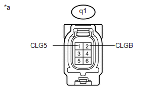
D87-19 (CLG8) - q1-1 (CLG5) |
Always |
Below 1 Ω |
|
D87-20 (CG8B) - q1-2 (CLGB) |
Always |
Below 1 Ω |
|
D87-19 (CLG8) - Body ground |
Always |
10 kΩ or higher |
|
D87-20 (CG8B) - Body ground |
Always |
10 kΩ or higher |
|
q1-1 (CLG5) - Body ground |
Always |
10 kΩ or higher |
|
q1-2 (CLGB) - Body ground |
Always |
10 kΩ or higher |
| NG |
|
REPAIR OR REPLACE HARNESS OR CONNECTOR |
|
|
6. |
INSPECT OUTSIDE ELECTRICAL KEY OSCILLATOR (for Rear Side) |
|
(a) Measure the resistance according to the value(s) in the table below. Standard Resistance:
Text in Illustration
|
|
| OK |
|
REPLACE CERTIFICATION ECU (SMART KEY ECU ASSEMBLY) (See page
|
| NG |
|
|
7. |
CHECK HARNESS AND CONNECTOR (BACK DOOR OPENER SWITCH - BODY GROUND) |
|
(a) Disconnect the back door opener switch assembly connector. |
|
(b) Measure the resistance according to the value(s) in the table below.
Standard Resistance:
|
Tester Connection |
Condition |
Specified Condition |
|---|---|---|
|
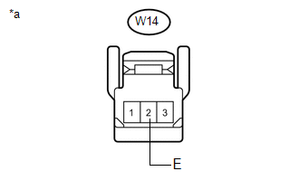
W14-2 (E) - Body ground |
Always |
Below 1 Ω |
Text in Illustration
|
*a |
Front view of wire harness connector (to Back Door Opener Switch Assembly)) |
| OK |
|
| NG |
|
REPAIR OR REPLACE HARNESS OR CONNECTOR |
|
|
|