- Engine switch off
- All doors closed
- Key not in cabin
| Last Modified: 08-28-2024 | 6.11:8.1.0 | Doc ID: RM100000000VJJX |
| Model Year Start: 2016 | Model: Sienna | Prod Date Range: [12/2015 - ] |
| Title: THEFT DETERRENT / KEYLESS ENTRY: SMART KEY SYSTEM(for Entry Function): TERMINALS OF ECU; 2016 - 2020 MY Sienna [12/2015 - ] | ||
TERMINALS OF ECU
1. CHECK CERTIFICATION ECU (SMART KEY ECU ASSEMBLY)
(a) Disconnect the D88 certification ECU (smart key ECU assembly) connector.
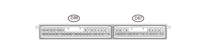
(b) Measure the voltage and resistance according to the value(s) in the table below.
HINT:
Measure the values on the wire harness side with the connector disconnected.
|
Terminal No. (Symbol) |
Wiring Color |
Terminal Description |
Condition |
Specified Condition |
|---|---|---|---|---|
|
D88-1 (+B) - Body ground |
G - Body ground |
+B power supply |
Always |
11 to 14 V |
|
D88-15 (E) - Body ground |
W-B - Body ground |
Ground |
Always |
Below 1 Ω |
|
D88-17 (CUTB) - Body ground |
B - Body ground |
Dark current cut fuse pin input signal |
Always |
11 to 14 V |
If the result is not as specified, there may be a malfunction in the wire harness.
(c) Reconnect the D88 certification ECU (smart key ECU assembly) connector.
(d) Measure the voltage and check for pulses according to the value(s) in the table below.
|
Terminal No. (Symbol) |
Wiring Color |
Terminal Description |
Condition |
Specified Condition |
|---|---|---|---|---|
|
D88-3 (CLG1) - D88-15 (E) |
G - W-B |
Door electrical key oscillator (for driver side) sensor signal |
|
No pulse generation |
|
D88-3 (CLG1) - D88-15 (E) |
G - W-B |
Door electrical key oscillator (for driver side) sensor signal |
|
Pulse generation |
|
D88-4 (CG1B) - D88-15 (E) |
R - W-B |
Door electrical key oscillator (for driver side) sensor signal |
|
No pulse generation |
|
D88-4 (CG1B) - D88-15 (E) |
R - W-B |
Door electrical key oscillator (for driver side) sensor signal |
|
Pulse generation |
|
D88-5 (CLG2) - D88-15 (E) |
P - W-B |
Door electrical key oscillator (for front passenger side) sensor signal |
|
No pulse generation |
|
D88-5 (CLG2) - D88-15 (E) |
P - W-B |
Door electrical key oscillator (for front passenger side) sensor signal |
|
Pulse generation |
|
D88-6 (CG2B) - D88-15 (E) |
V - W-B |
Door electrical key oscillator (for front passenger side) sensor signal |
|
No pulse generation |
|
D88-6 (CG2B) - D88-15 (E) |
V - W-B |
Door electrical key oscillator (for front passenger side) sensor signal |
|
Pulse generation |
|
D88-7 (CLG5) - D88-15 (E) |
R - W-B |
Indoor electrical key oscillator (for front floor) sensor signal |
|
No pulse generation |
|
D88-7 (CLG5) - D88-15 (E) |
R - W-B |
Indoor electrical key oscillator (for front floor) sensor signal |
|
Pulse generation |
|
D88-8 (CG5B) - D88-15 (E) |
W - W-B |
Indoor electrical key oscillator (for front floor) sensor signal |
|
No pulse generation |
|
D88-8 (CG5B) - D88-15 (E) |
W - W-B |
Indoor electrical key oscillator (for front floor) sensor signal |
|
Pulse generation |
|
D88-16 (IG) - Body ground |
B - Body ground |
IG power supply |
Engine switch off |
Below 1 V |
|
D88-16 (IG) - Body ground |
B - Body ground |
IG power supply |
Engine switch on (IG) |
11 to 14 V |
|
D88-18 (TSW1) - D88-15 (E) |
B - W-B |
Lock sensor (for driver side) detection signal |
|
Pulse generation |
|
D88-18 (TSW1) - D88-15 (E) |
B - W-B |
Lock sensor (for driver side) detection signal |
|
Below 2 V |
|
D88-19 (TSW2) - D88-15 (E) |
Y - W-B |
Lock sensor (for front passenger side) detection signal |
|
Pulse generation |
|
D88-19 (TSW2) - D88-15 (E) |
Y - W-B |
Lock sensor (for front passenger side) detection signal |
|
Below 2 V |
|
D88-20 (SEN1) - D88-15 (E) |
GR - W-B |
Touch sensor (for driver side) detection signal |
|
Pulse generation |
|
D88-20 (SEN1) - D88-15 (E) |
GR - W-B |
Touch sensor (for driver side) detection signal |
|
Below 2 V |
|
D88-21 (SEN2) - D88-15 (E) |
BR - W-B |
Touch sensor (for front passenger side) detection signal |
|
Pulse generation |
|
D88-21 (SEN2) - D88-15 (E) |
BR - W-B |
Touch sensor (for front passenger side) detection signal |
|
Below 2 V |
|
D88-22 (TSW5) - D88-15 (E) |
L - W-B |
Back door opener switch assembly (opener switch) signal |
Back door opener switch assembly (opener switch) not pushed |
Pulse generation |
|
D88-22 (TSW5) - D88-15 (E) |
L - W-B |
Back door opener switch assembly (opener switch) signal |
Back door opener switch assembly (opener switch) pushed |
Below 1 V |
|
D88-23 (TSW6) - D88-15 (E) |
Y - W-B |
Back door opener switch assembly (lock switch) signal |
Back door opener switch assembly (lock switch) not pushed |
Pulse generation |
|
D88-23 (TSW6) - D88-15 (E) |
Y - W-B |
Back door opener switch assembly (lock switch) signal |
Back door opener switch assembly (lock switch) pushed |
Below 1 V |
|
D88-24 (CLG6) - D88-15 (E) |
V - W-B |
Indoor electrical key oscillator (for center floor) sensor signal |
|
No pulse generation |
|
D88-24 (CLG6) - D88-15 (E) |
V - W-B |
Indoor electrical key oscillator (for center floor) sensor signal |
|
Pulse generation |
|
D88-25 (CG6B) - D88-15 (E) |
P - W-B |
Indoor electrical key oscillator (for center floor) sensor signal |
|
No pulse generation |
|
D88-25 (CG6B) - D88-15 (E) |
P - W-B |
Indoor electrical key oscillator (for center floor) sensor signal |
|
Pulse generation |
|
D88-26 (CLG7) - D88-15 (E) |
L - W-B |
Indoor electrical key oscillator (for rear floor) sensor signal |
|
No pulse generation |
|
D88-26 (CLG7) - D88-15 (E) |
L - W-B |
Indoor electrical key oscillator (for rear floor) sensor signal |
|
Pulse generation |
|
D88-27 (CG7B) - D88-15 (E) |
LG - W-B |
Indoor electrical key oscillator (for rear floor) sensor signal |
|
No pulse generation |
|
D88-27 (CG7B) - D88-15 (E) |
LG - W-B |
Indoor electrical key oscillator (for rear floor) sensor signal |
|
Pulse generation |
|
D88-32 (POS1) - D88-15 (E) |
Y - W-B |
Lock or unlock sensor (for driver side) output signal |
Engine switch off |
9 to 14 V |
|
D88-32 (POS1) - D88-15 (E) |
Y - W-B |
Lock or unlock sensor (for driver side) output signal |
Engine switch on (IG) |
Below 2 V |
|
D88-33 (POS2) - D88-15 (E) |
LG - W-B |
Lock or unlock sensor (for front passenger side) output signal |
Engine switch off |
9 to 14 V |
|
D88-33 (POS2) - D88-15 (E) |
LG - W-B |
Lock or unlock sensor (for front passenger side) output signal |
Engine switch on (IG) |
Below 2 V |
|
D87-5 (RCO) - D88-15 (E) |
V - W-B |
Door control receiver power source |
|
Below 1 V |
|
D87-5 (RCO) - D88-15 (E) |
V - W-B |
Door control receiver power source |
|
4.5 to 5.5 V |
|
D87-15 (RDA) - D88-15 (E) |
Y - W-B |
Door control receiver data input signal |
Engine switch off, all doors closed and transmitter switch not pressed |
11 to 14 V pulse generation at regular intervals |
|
Engine switch off, all doors closed and transmitter switch pressed |
Pulse generation |
|||
|
D87-16 (RSSI) - D88-15 (E) |
R - W-B |
Door control receiver electric wave existence signal |
|
11 to 14 V |
|
D87-16 (RSSI) - D88-15 (E) |
R - W-B |
Door control receiver electric wave existence signal |
|
Below 2 V |
|
D87-19 (CLG8) - D88-15 (E) |
P - W-B |
Outside electrical key oscillator (for rear side) sensor signal |
|
No pulse generation |
|
D87-19 (CLG8) - D88-15 (E) |
P - W-B |
Outside electrical key oscillator (for rear side) sensor signal |
|
Pulse generation |
|
D87-20 (CG8B) - D88-15 (E) |
V - W-B |
Outside electrical key oscillator (for rear side) sensor signal |
|
No pulse generation |
|
D87-20 (CG8B) - D88-15 (E) |
V - W-B |
Outside electrical key oscillator (for rear side) sensor signal |
|
Pulse generation |
If the result is not as specified, the certification ECU (smart key ECU assembly) may have a malfunction.
2. CHECK INSTRUMENT PANEL JUNCTION BLOCK ASSEMBLY AND MAIN BODY ECU
(a) Turn the engine switch off.
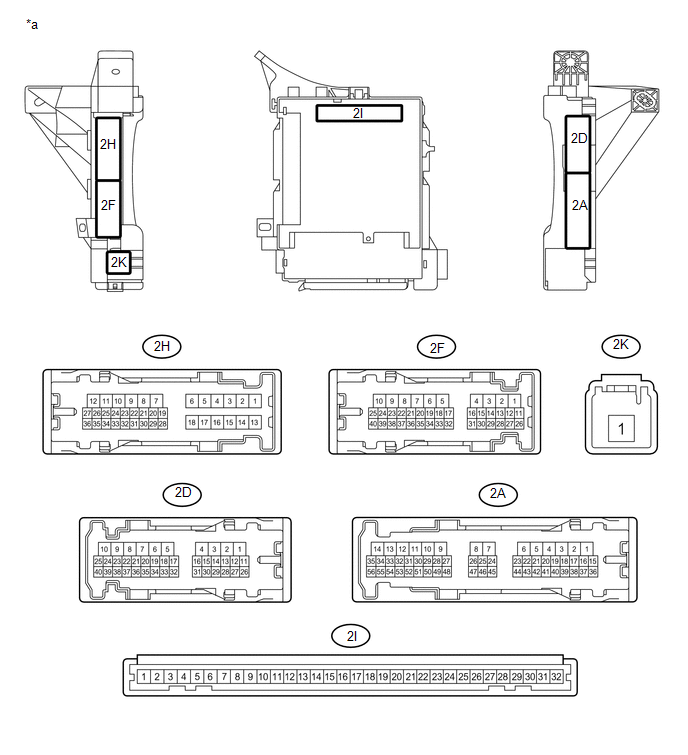
|
*a |
Instrument Panel Junction Block Assembly |
- |
- |
(b) Remove the main body ECU from the instrument panel junction block assembly (See page
![2016 - 2020 MY Sienna [12/2015 - ]; POWER DISTRIBUTION: MAIN BODY ECU: REMOVAL](/t3Portal/stylegraphics/info.gif) ).
).
HINT:
The instrument panel junction block assembly connectors must all be connected.
(c) Measure the voltage and resistance according to the value(s) in the table below.
|
Terminal No. (symbol) |
Wiring Color |
Terminal Description |
Condition |
Specified Condition |
|---|---|---|---|---|
|
2I-2 (FLCY) - Body ground |
- |
Front door courtesy light switch LH input |
Front door LH CLOSED (off) → OPEN (on) |
10 kΩ or higher → Below 1 Ω |
|
2I-4 (FRCY) - Body ground |
- |
Front door courtesy light switch RH input |
Front door RH CLOSED (off) → OPEN (on) |
10 kΩ or higher → Below 1 Ω |
|
2I-11 (GND1) - Body ground |
- |
Ground |
Always |
Below 1 Ω |
|
2I-29 (ACC) - Body ground |
- |
Ignition power supply (ACC signal) |
Engine switch ACC → off |
11 to 14 V → Below 1 V |
|
2I-30 (BECU) - Body ground |
- |
+B (power system signal system) power supply |
Always |
11 to 14 V |
|
2I-31 (ALTB) - Body ground |
- |
+B (power system alternator system) power supply |
Always |
11 to 14 V |
|
2I-32 (IG) - Body ground |
- |
Ignition power supply (IG signal) |
Engine switch ON → off |
11 to 14 V → Below 1 V |
|
D12-3 (LCTY) - Body ground |
GR - Body ground |
Rear door courtesy light LH switch input |
Rear door CLOSED (off) → OPEN (on) |
10 kΩ or higher → Below 1 Ω |
|
D13-6 (RCTY) - Body ground |
L - Body ground |
Rear door courtesy light RH switch input |
Rear door CLOSED (off) → OPEN (on) |
10 kΩ or higher → Below 1 Ω |
|
D13-19 (BCTY) - Body ground |
GR - Body ground |
Back door courtesy light switch input |
Back door CLOSED (off) → OPEN (on) |
10 kΩ or higher → Below 1 Ω |
If the result is not as specified, there may be a malfunction in the wire harness or the instrument panel junction block assembly.
(d) Reinstall the main body ECU (See page
).
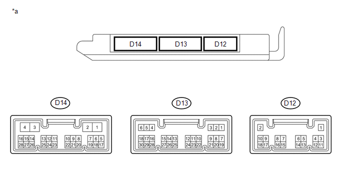
|
*a |
Main Body ECU |
- |
- |
(e) Reconnect the D12 and D13 main body ECU connectors.
(f) Measure the resistance according to the value(s) in the table below.
|
Terminal No. (symbol) |
Wiring Color |
Terminal Description |
Condition |
Specified Condition |
|---|---|---|---|---|
|
D12-3 (LCTY) - Body ground |
GR - Body ground |
Rear door courtesy light LH switch input |
Rear door CLOSED (off) → OPEN (on) |
10 kΩ or higher → Below 1Ω |
|
D13-6 (RCTY) - Body ground |
L - Body ground |
Rear door courtesy light RH switch input |
Rear door CLOSED (off) → OPEN (on) |
10 kΩ or higher → Below 1Ω |
|
D13-19 (BCTY) - Body ground |
GR - Body ground |
Back door courtesy light switch input |
Back door CLOSED (off) → OPEN (on) |
10 kΩ or higher → Below 1Ω |
If the result is not as specified, there may be a malfunction in the wire harness.
HINT:
Measure the values on the wire harness side with the connectors disconnected.
(g) Reconnect the main body ECU connectors.
(h) Measure the voltage and check for pulses according to the value(s) in the table below.
|
Terminal No. (Symbol) |
Wiring Color |
Terminal Description |
Condition |
Specified Condition |
|---|---|---|---|---|
|
2D-2 (ACTD) - Body ground |
R - Body ground |
Driver side door lock motor unlock drive output |
Multiplex network master switch (door control switch) or driver side door key cylinder off |
Below 1 V |
|
2D-2 (ACTD) - Body ground |
R - Body ground |
Driver side door lock motor unlock drive output |
Multiplex network master switch (door control switch) or driver side door key cylinder unlocked |
11 to 14 V |
|
2D-3 (ACT+) - Body ground |
P - Body ground |
Door lock motor lock drive output (all doors) |
Multiplex network master switch (door control switch) or driver side door key cylinder off |
Below 1 V |
|
2D-3 (ACT+) - Body ground |
P - Body ground |
Door lock motor lock drive output (all doors) |
Multiplex network master switch (door control switch) or driver side door key cylinder locked |
11 to 14 V |
|
2D-1 (ACT-) - Body ground |
SB - Body ground |
Door lock motor unlock drive output(except driver side) |
Multiplex network master switch (door control switch) or driver side door key cylinder off |
Below 1 V |
|
2D-1 (ACT-) - Body ground |
SB - Body ground |
Door lock motor unlock drive output(except driver side) |
Multiplex network master switch (door control switch) or driver side door key cylinder unlocked |
11 to 14 V |
|
2H-36 (FRCY) - Body ground |
GR - Body ground |
Front passenger side door courtesy switch input |
Front passenger side door open |
Below 1 V |
|
2H-36 (FRCY) - Body ground |
GR - Body ground |
Front passenger side door courtesy switch input |
Front passenger side door closed |
11 to 14 V |
|
2H-34 (FLCY) - Body ground |
P - Body ground |
Driver door courtesy switch input |
Driver door open |
Below 1 V |
|
2H-34 (FLCY) - Body ground |
P - Body ground |
Driver side door courtesy switch input |
Driver door closed |
11 to 14 V |
|
2H-33 (LSWL) - Body ground |
LG - Body ground |
Rear door LH lock position switch input |
Rear door LH unlocked |
Below 1 V |
|
2H-33 (LSWL) - Body ground |
LG - Body ground |
Rear door LH lock position switch input |
Engine switch off, all doors closed and rear door LH locked |
Pulse generation |
|
D12-3 (LCTY) - Body ground |
GR - Body ground |
Rear door LH courtesy light switch input |
Rear door LH open |
Below 1 V |
|
D12-3 (LCTY) - Body ground |
GR - Body ground |
Rear door LH courtesy light switch input |
Rear door LH closed |
11 to 14 V |
|
D13-6 (RCTY) - Body ground |
L - Body ground |
Rear door RH courtesy light switch input |
Rear door RH open |
Below 1 V |
|
D13-6 (RCTY) - Body ground |
L - Body ground |
Rear door RH courtesy light switch input |
Rear door RH closed |
11 to 14 V |
|
D13-7 (LSFL) - Body ground |
V - Body ground |
Driver door lock position switch input |
Driver door unlocked |
Below 1 V |
|
D13-7 (LSFL) - Body ground |
V - Body ground |
Driver door lock position switch input |
Engine switch off, all doors closed and driver door locked |
Pulse generation |
|
D13-9 (L1) - Body ground |
B - Body ground |
Front passenger side door control switch input |
Front passenger side door control switch locked |
Below 1 V |
|
D13-9 (L1) - Body ground |
B - Body ground |
Front passenger side door control switch input |
Front passenger side door control switch off |
Pulse generation |
|
D13-10 (UL1) - Body ground |
G - Body ground |
Front passenger side door control switch input |
Front passenger side door control switch unlocked |
Below 1 V |
|
D13-10 (UL1) - Body ground |
G - Body ground |
Front passenger side door control switch input |
Front passenger side door control switch off |
Pulse generation |
|
D13-11 (L2) - Body ground |
LG - Body ground |
Driver side door key-linked lock input |
Driver side door key cylinder turned to locked |
Below 1 V |
|
D13-11 (L2) - Body ground |
LG - Body ground |
Driver side door key-linked lock input |
Driver side door key cylinder off |
11 to 14 V |
|
D13-18 (LSFR) - Body ground |
Y - Body ground |
Front passenger side door lock position switch input |
Front passenger side door unlocked |
Below 1 V |
|
D13-18 (LSFR) - Body ground |
Y - Body ground |
Front passenger side door lock position switch input |
Engine switch off, all doors closed and front passenger side door locked |
Pulse generation |
|
D13-19 (BCTY) - Body ground |
GR - Body ground |
Back door courtesy light switch input |
Back door open |
Below 1 V |
|
D13-19 (BCTY) - Body ground |
GR - Body ground |
Back door courtesy light switch input |
Back door closed |
11 to 14 V |
|
D13-24 (UL3) - Body ground |
L - Body ground |
Driver side door key-linked unlock input |
Driver side door key cylinder turned to unlocked |
Below 1 V |
|
D13-24 (UL3) - Body ground |
L - Body ground |
Driver side door key-linked unlock input |
Driver side door key cylinder off |
11 to 14 V |
|
D14-2 (LSWR) - Body ground |
L - Body ground |
Rear door RH lock position switch input |
Rear door RH unlocked |
Below 1 V |
|
D14-2 (LSWR) - Body ground |
L - Body ground |
Rear door RH lock position switch input |
Engine switch off, all doors closed and rear door RH locked |
11 to 14 V |
If the result is not as specified, the main body ECU or instrument panel junction block assembly may have a malfunction.
3. CHECK SLIDE DOOR MOTOR UNIT LH (POWER SLIDE DOOR ECU LH)
(a) Disconnect the J9 connector from the power slide door ECU LH.

(b) Measure the voltage and resistance according to the value(s) in the table below.
|
Terminal No. (Symbol) |
Wiring Color |
Terminal Description |
Condition |
Specified Condition |
|---|---|---|---|---|
|
J9-12 (ECUB) - J9-1 (GND) |
SB - W-B |
Power supply |
Always |
11 to 14 V |
|
J9-7 (B) - J9-1 (GND) |
LG - W-B |
Power supply |
Always |
11 to 14 V |
|
J9-4 (IG) - J9-1 (GND) |
B - W-B |
Power supply |
Engine switch on (IG) |
11 to 14 V |
|
J9-1 (GND) - Body ground |
W-B - Body ground |
Ground |
Always |
Below 1 Ω |
|
J9-9 (OSW) - J9-2 (OSWG) |
G - V |
Power slide door switch LH input |
Slide door outside handle LH pulled |
Below 1 Ω |
|
Slide door outside handle LH not operated |
10 kΩ or higher |
|||
|
J9-11 (MPX1) - Body ground |
R - Body ground |
CAN |
Always |
10 kΩ or higher |
|
J9-5 (MPX2) - Body ground |
W - Body ground |
CAN |
Always |
10 kΩ or higher |
4. CHECK SLIDE DOOR MOTOR UNIT RH (POWER SLIDE DOOR ECU RH)
(a) Disconnect the I8 connector from the power slide door ECU RH.

(b) Measure the voltage and resistance according to the value(s) in the table below.
|
Terminal No. (Symbol) |
Wiring Color |
Terminal Description |
Condition |
Specified Condition |
|---|---|---|---|---|
|
I8-7 (ECUB) - I8-6 (GND) |
SB - W-B |
Power supply |
Always |
11 to 14 V |
|
I8-12 (B) - I8-6 (GND) |
LG - W-B |
Power supply |
Always |
11 to 14 V |
|
I8-3 (IG) - I8-6 (GND) |
B - W-B |
Power supply |
Engine switch on (IG) |
11 to 14 V |
|
I8-6 (GND) - Body ground |
W-B - Body ground |
Ground |
Always |
Below 1 Ω |
|
I8-10 (OSW) - I8-5 (OSWG) |
G - V |
Power slide door switch RH input |
Slide door outside handle RH pulled |
Below 1 Ω |
|
Slide door outside handle RH not operated |
10 kΩ or higher |
|||
|
I8-8 (MPX1) - Body ground |
R - Body ground |
CAN |
Always |
10 kΩ or higher |
|
I8-2 (MPX2) - Body ground |
W - Body ground |
CAN |
Always |
10 kΩ or higher |
|
|
|