|
Last Modified: 08-28-2024 |
6.11:8.1.0 |
Doc ID: RM100000000VJJN |
|
Model Year Start: 2016 |
Model: Sienna |
Prod Date Range: [12/2015 - 08/2016] |
|
Title: THEFT DETERRENT / KEYLESS ENTRY: SMART KEY SYSTEM(for Start Function): Power Source Mode does not Change to ON (IG); 2016 MY Sienna [12/2015 - 08/2016] |
|
Power Source Mode does not Change to ON (IG)
|
DESCRIPTION
When the engine switch is pushed with the key in the cabin, the power management control ECU receives signals to switch the power source mode.
Use this troubleshooting procedure when the power source mode does not change to on (IG) but does change to on (ACC).
HINT:
-
When the power management control ECU is replaced with a new one and the cable is connected to the negative (-) battery terminal, the power source mode changes to on (IG).
-
When the battery cable is disconnected and reconnected, the power source mode returns to the mode it was in before the battery cable was disconnected.
WIRING DIAGRAM
Refer to "Power Source Mode does not Change to on (IG and ACC)" (See page
![2016 MY Sienna [12/2015 - 08/2016]; THEFT DETERRENT / KEYLESS ENTRY: SMART KEY SYSTEM(for Start Function): Power Source Mode does not Change to ON (IG and ACC)+](/t3Portal/stylegraphics/info.gif) ).
).
CAUTION / NOTICE / HINT
Related Data List and Active Test Items
|
Problem Symptom
|
Data List Item
|
Active Test Item
|
|
Power source mode does not change to on (IG) but does change to on (ACC)
|
Power Source Control
-
Power Supply Condition
-
IG1 Relay Monitor(Inside)
-
IG2 Relay Monitor(Inside)
-
IG1 Relay Monitor(Outside)
-
IG2 Relay Monitor(Outside)
-
Latch Circuit
-
IG1 Circuit
-
IG2 Circuit
|
-
|
PROCEDURE
|
OK
|

|
|
|
2.
|
CHECK HARNESS AND CONNECTOR (BATTERY - POWER MANAGEMENT CONTROL ECU)
|
|
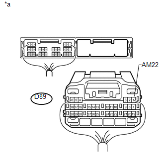
(a) Disconnect the D89 power management control ECU connector.
|
|
(b) Measure the voltage according to the value(s) in the table below.
Standard Voltage:
|
Tester Connection
|
Condition
|
Specified Condition
|
|
D89-1 (AM22) - Body ground
|
Always
|
9.5 to 14 V
|
Text in Illustration
|
*a
|
Rear view of wire harness connector
(to Power Management Control ECU)
|
| NG |

|
REPAIR OR REPLACE HARNESS OR CONNECTOR IN CIRCUIT CONNECTED TO POWER SOURCE
|
|
OK
|
|
|
|
(a) Remove the IG2 relay from the engine room relay block.
(b) Inspect IG2 relay (See page
).
| NG |
|
REPLACE IG2 RELAY
|
|
OK
|
|
|
|
|
4.
|
INSPECT INSTRUMENT PANEL JUNCTION BLOCK ASSEMBLY (IG1 NO. 1, IG1 NO. 2, IG1 NO. 3 AND IG1 NO. 4 RELAYS)
|
|
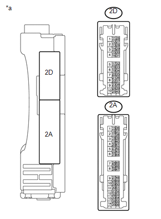
(a) Disconnect the 2A and 2D instrument panel junction block assembly connectors.
|
|
(b) Measure the resistance according to the value(s) in the table below.
Standard Resistance:
|
Tester Connection
|
Condition
|
Specified Condition
|
|
2A-16 - 2D-7
|
20°C (68°F)
|
50.63 to 123.75 Ω
|
Text in Illustration
|
*a
|
Component without harness connected
(Instrument Panel Junction Block Assembly)
|
| NG |
|
REPLACE INSTRUMENT PANEL JUNCTION BLOCK ASSEMBLY
|
|
OK
|
|
|
|
|
5.
|
CHECK HARNESS AND CONNECTOR (POWER MANAGEMENT CONTROL ECU - INSTRUMENT PANEL JUNCTION BLOCK ASSEMBLY)
|
(a) Disconnect the D89 power management control ECU connector.
(b) Disconnect the 2A instrument panel block assembly connector.
(c) Measure the resistance according to the value(s) in the table below.
Standard Resistance:
|
Tester Connection
|
Condition
|
Specified Condition
|
|
D89-20 (IG1D) - 2A-16
|
Always
|
Below 1 Ω
|
|
D89-20 (IG1D) - Body ground
|
Always
|
10 kΩ or higher
|
| NG |
|
REPAIR OR REPLACE HARNESS OR CONNECTOR
|
|
OK
|
|
|
|
|
6.
|
CHECK HARNESS AND CONNECTOR (INSTRUMENT PANEL JUNCTION BLOCK ASSEMBLY - BODY GROUND)
|
(a) Disconnect the 2D instrument panel junction block assembly connector.
(b) Measure the resistance according to the value(s) in the table below.
Standard Resistance:
|
Tester Connection
|
Condition
|
Specified Condition
|
|
2D-7 - Body ground
|
Always
|
Below 1 Ω
|
| NG |
|
REPAIR OR REPLACE HARNESS OR CONNECTOR
|
|
OK
|
|
|
|
|
7.
|
CHECK HARNESS AND CONNECTOR (POWER MANAGEMENT CONTROL ECU - IG2 RELAY)
|
(a) Disconnect the A35 power management control ECU connector.
(b) Remove the IG2 relay from the engine room relay block.
(c) Measure the resistance according to the value(s) in the table below.
Standard Resistance:
|
Tester Connection
|
Condition
|
Specified Condition
|
|
A35-8 (IG2D) - 1 (IG2 relay terminal)
|
Always
|
Below 1 Ω
|
|
A35-8 (IG2D) - Body ground
|
Always
|
10 kΩ or higher
|
| NG |
|
REPAIR OR REPLACE HARNESS OR CONNECTOR
|
|
OK
|
|
|
|
|
8.
|
CHECK HARNESS AND CONNECTOR (IG2 RELAY - BODY GROUND)
|
|
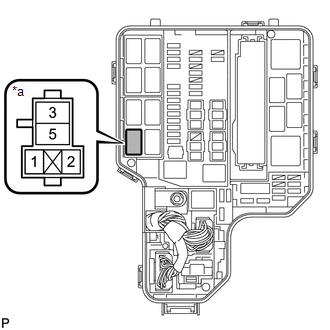
(a) Remove the IG2 relay from the engine room relay block.
|
|
(b) Measure the resistance according to the value(s) in the table below.
Standard Resistance:
|
Tester Connection
|
Condition
|
Specified Condition
|
|
2 (IG2 relay terminal) - Body ground
|
Always
|
Below 1 Ω
|
Text in Illustration
|
*a
|
Component without relay connected
(IG2 Relay Terminal)
|
| NG |
|
REPAIR OR REPLACE HARNESS OR CONNECTOR
|
|
OK
|
|
|
|
|
9.
|
INSPECT POWER MANAGEMENT CONTROL ECU
|
|
OK
|
|
|
|
| OK |
|
SYSTEM RETURNED TO NORMAL (PROBLEM OCCURRED DUE TO BAD CONNECTION, BUT RETURNED TO NORMAL BY RECONNECTING CONNECTOR)
|
| NG |
|
CHECK RELAY CONTACT CIRCUIT
|
|