|
Last Modified: 08-28-2024 |
6.11:8.1.0 |
Doc ID: RM100000000VJJM |
|
Model Year Start: 2016 |
Model: Sienna |
Prod Date Range: [12/2015 - 08/2016] |
|
Title: THEFT DETERRENT / KEYLESS ENTRY: SMART KEY SYSTEM(for Start Function): Power Source Mode does not Change to ON (IG and ACC); 2016 MY Sienna [12/2015 - 08/2016] |
|
Power Source Mode does not Change to ON (IG and ACC)
|
DESCRIPTION
When the key is in the vehicle and the engine switch is pressed, the power management control ECU receives a signal and changes the power source mode.
HINT:
-
When the power management control ECU is replaced with a new one and the cable is connected to the negative (-) battery terminal, the power source mode changes to on (IG).
-
When the battery cable is disconnected and reconnected, the power source mode returns to the mode it was in before the battery cable was disconnected.
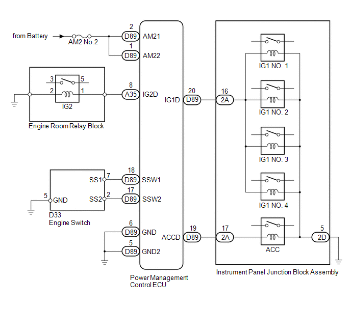
WIRING DIAGRAM
CAUTION / NOTICE / HINT
Related Data List and Active Test Items
|
Problem Symptom
|
Data List Item
|
Active Test Item
|
|
Power source mode does not change to on (IG) or on (ACC)
|
Power Source Control
-
Start Switch1
-
Start Switch2
-
Power Supply Condition
-
IG1 Relay Monitor(Inside)
-
IG2 Relay Monitor(Inside)
-
IG1 Relay Monitor(Outside)
-
IG2 Relay Monitor(Outside)
-
Latch Circuit
-
ACC Relay Monitor
|
-
|
PROCEDURE
(a) Using the Techstream, confirm the output of DTCs for all systems.
OK:
No DTCs are output.
NOTICE:
-
When using the Techstream with the engine switch off, perform either of the following: 1) Turn a courtesy light switch on and off at intervals of 1.5 seconds or less until communication between the Techstream and vehicle begins, or 2) connect the Techstream to the vehicle, select the vehicle type under manual mode, and then enter the following menus: Body Electrical / Smart Key / Trouble Codes.
-
Make sure that no DTCs are output. If any DTCs are output, proceed to the Diagnostic Trouble Code Chart.
|
OK
|

|
|
|
2.
|
CHECK WIRELESS DOOR LOCK CONTROL SYSTEM
|
(a) Check that the wireless lock and unlock functions operate normally.
OK:
Wireless lock and unlock functions operate normally.
HINT:
If the wireless lock and unlock functions operate normally, it can be determined that some functions of the key and certification ECU operate normally.
|
OK
|
|
|
|
|
3.
|
CHECK SMART KEY SYSTEM
|
|
(a) Remove the battery of the electrical key transmitter.
|
|
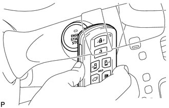
(b) With the brake pedal depressed, touch the key to the engine switch.
(c) Depress and hold the engine switch for a maximum of 15 seconds and check if the engine can be started.
OK:
The engine can be started.
HINT:
-
If the engine can be started, it is clear that the key is not being detected properly inside the vehicle. There may be a problem with the formation of the interior detection area, a problem with the indoor electrical key antenna (reception problem), or wave interference.
-
If the engine cannot be started, there is a problem with the engine switch, power management control ECU or a related wire harness.
|
NG
|
|
|
|
|
4.
|
READ VALUE USING TECHSTREAM (START SWITCH 1, 2)
|
(a) Connect the Techstream to the DLC3.
(b) Turn the Techstream on.
NOTICE:
When using the Techstream with the engine switch off, perform the following: Turn a courtesy light switch on and off at intervals of 1.5 seconds or less until communication between the Techstream and vehicle begins.
(c) Enter the following menus: Body Electrical / Power Source Control / Data List.
(d) According to the display on the Techstream, read the Data List.
Power Source Control
|
Tester Display
|
Measurement Item/Range
|
Normal Condition
|
Diagnostic Note
|
|
Start Switch1
|
Condition of engine switch contact 1/ON or OFF
|
ON: Engine switch pressed
OFF: Engine switch not pressed
|
-
If the engine switch is pressed for a short time, the display may not change.
-
Use this item to determine whether the engine switch input signal is malfunctioning.
|
|
Start Switch2
|
Condition of engine switch contact 2/ON or OFF
|
ON: Engine switch pressed
OFF: Engine switch not pressed
|
-
This is the backup for engine switch 1.
-
Behaves the same way as engine switch 1.
|
OK:
The display changes in response to the operation of the engine switch.
|
OK
|
|
|
|
|
5.
|
CHECK HARNESS AND CONNECTOR (BATTERY - POWER MANAGEMENT CONTROL ECU)
|
![2016 - 2020 MY Sienna [12/2015 - ]; THEFT DETERRENT / KEYLESS ENTRY: SMART KEY SYSTEM(for Start Function): B2271; Ignition Hold Monitor Malfunction+](/t3Portal/stylegraphics/info.gif)
| NG |

|
REPAIR OR REPLACE HARNESS OR CONNECTOR IN CIRCUIT CONNECTED TO POWER SOURCE
|
|
OK
|
|
|
|
|
6.
|
CHECK HARNESS AND CONNECTOR (POWER MANAGEMENT CONTROL ECU - BODY GROUND)
|
| NG |
|
REPAIR OR REPLACE HARNESS OR CONNECTOR
|
|
OK
|
|
|
|
|
7.
|
INSPECT POWER MANAGEMENT CONTROL ECU
|
(a) Connect the Techstream to the DLC3.
(b) Turn the Techstream on.
NOTICE:
When using the Techstream with the engine switch off, perform the following: Turn a courtesy light switch on and off at intervals of 1.5 seconds or less until communication between the Techstream and vehicle begins.
(c) Enter the following menus: Body Electrical / Power Source Control / Data List.
(d) Read the Data List and check that the display changes according to the changes in the power source mode when the engine switch is pushed.
Power Source Control
|
Tester Display
|
Measurement Item/Range
|
Normal Condition
|
Diagnostic Note
|
|
Power Supply Condition
|
State of power supply/IG2 ON, ST ON, All OFF, IG1 ON or ACC ON
|
All OFF: Engine switch off (power supply off) ACC ON: Engine switch on (ACC) (ACC relay on)
IG1 ON: Engine switch on (IG) (IG1 relay on)
IG2 ON: Engine switch on (IG) (IG2 relay on)
ST ON: Cranking engine (ST request signal on)
|
Since IG1 ON and IG2 ON turn "ON" at approximately the same time, IG2 ON may not be displayed.
|
OK:
Display changes according to the changes in the power source mode when the engine switch is pushed.
(e) Measure the voltage according to the value(s) in the table below.
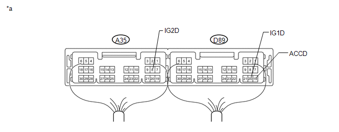
Text in Illustration
|
*a
|
Component with harness connected
(Power Management Control ECU)
|
-
|
-
|
Standard Voltage:
|
Tester Connection
|
Switch Condition
|
Specified Condition
|
|
D89-20 (IG1D) - Body ground
|
Engine switch off
|
1 V or less
|
|
Engine switch on (ACC)*1
|
|
Engine switch on (IG)*2
|
9 V or higher
|
|
A35-8 (IG2D) - Body ground
|
Engine switch off
|
1 V or less
|
|
Engine switch on (ACC)*1
|
|
Engine switch on (IG)*2
|
9 V or higher
|
|
D89-19 (ACCD) - Body ground
|
Engine switch off
|
1 V or less
|
|
Engine switch on (ACC)*1
|
8.5 V or higher
|
|
Engine switch on (IG)*2
|
8.5 V or higher
|
HINT:
-
*1: To turn the engine switch on (ACC), carry the key and press the engine switch with the shift lever in P and the brake pedal released.
-
*2: To turn the engine switch on (IG), carry the key and press the engine switch twice with the shift lever in P and the brake pedal released.
|
OK
|
|
|
|
(a) Check that the power source mode changes to on (ACC) and on (IG) when operating the engine switch.
OK:
The power source mode changes to on (ACC) and on (IG) in response to the operation of the engine switch.
| NG |
|
CHECK RELAY CONTACT CIRCUIT
|
|
(a) Remove the engine switch.
|
|
(b) Measure the resistance according to the value(s) in the table below.
Standard Resistance:
|
Tester Connection
|
Switch Condition
|
Specified Condition
|
|
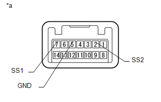
7 (SS1) - 5 (GND)
|
Engine switch not pushed
|
10 kΩ or higher
|
|
Engine switch pushed
|
Below 1 Ω
|
|
2 (SS2) - 5 (GND)
|
Engine switch not pushed
|
10 kΩ or higher
|
|
Engine switch pushed
|
Below 1 Ω
|
Text in Illustration
|
*a
|
Component without harness connected
(Engine Switch)
|
|
OK
|
|
|
|
|
10.
|
CHECK HARNESS AND CONNECTOR (POWER MANAGEMENT CONTROL ECU - ENGINE SWITCH)
|
(a) Disconnect the D89 power management control ECU connector.
(b) Disconnect the D33 engine switch connector.
(c) Measure the resistance according to the value(s) in the table below.
Standard Resistance:
|
Tester Connection
|
Condition
|
Specified Condition
|
|
D89-17 (SSW2) - D33-2 (SS2)
|
Always
|
Below 1 Ω
|
|
D89-18 (SSW1) - D33-7 (SS1)
|
|
D89-17 (SSW2) - Body ground
|
Always
|
10 kΩ or higher
|
|
D89-18 (SSW1) - Body ground
|
|
D33-5 (GND) - Body ground
|
Always
|
Below 1 Ω
|
| NG |
|
REPAIR OR REPLACE HARNESS OR CONNECTOR
|
|