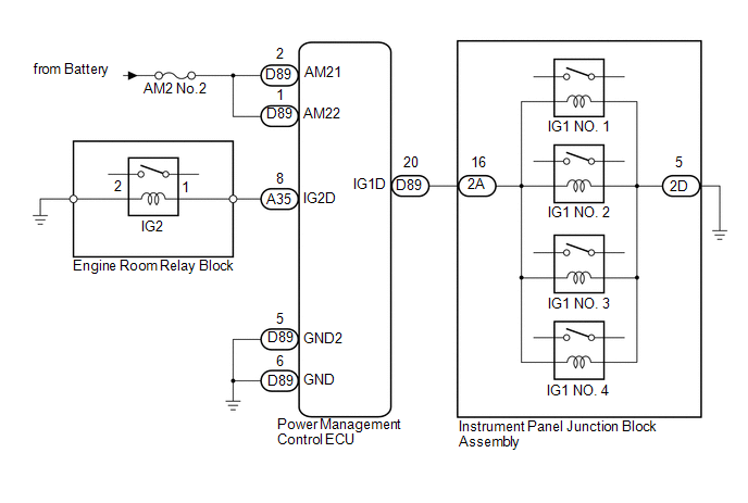
- The IG1 or IG2 drive circuit in the power management control ECU is malfunctioning.
- The IG hold circuit in the power management control ECU is malfunctioning.
| Last Modified: 08-28-2024 | 6.11:8.1.0 | Doc ID: RM100000000VJJG |
| Model Year Start: 2016 | Model: Sienna | Prod Date Range: [12/2015 - ] |
| Title: THEFT DETERRENT / KEYLESS ENTRY: SMART KEY SYSTEM(for Start Function): B2271; Ignition Hold Monitor Malfunction; 2016 - 2020 MY Sienna [12/2015 - ] | ||
|
DTC |
B2271 |
Ignition Hold Monitor Malfunction |
DESCRIPTION
This DTC is stored when a malfunction in the IG1 drive circuit, IG2 drive circuit or IG hold circuit in the power management control ECU is detected.
HINT:
- When the power management control ECU is replaced with a new one and the cable is connected to the negative (-) battery terminal, the power source mode changes to on (IG).
- When the battery cable is disconnected and reconnected, the power source returns to the mode it was in before the battery cable was disconnected.
|
DTC Code |
DTC Detection Condition |
Trouble Area |
DTC Output Confirmation Operation |
|---|---|---|---|
|
B2271 |
Either condition is met (1-trip detection logic*): |
|
Turn the engine switch on (IG). HINT: To turn the engine switch on (IG), carry the key and press the engine switch twice with the shift lever in P and the brake pedal released. |
- *: Only output while a malfunction is present and the engine switch is on (IG)
HINT:
- The IG1 and IG2 drive circuits activate the IG1 and IG2 relays.
- After the IG1 and IG2 drive circuits turn on, even if the power management control ECU operates incorrectly, the IG hold circuit maintains the engine switch on (IG) state.
Vehicle Condition and Fail-safe Function when Malfunction Detected
|
Vehicle Condition when Malfunction Detected |
Fail-safe Function when Malfunction Detected |
|---|---|
|
The power source mode is not allowed to change to on (IG) (the engine cannot be started). |
The power source mode cannot be changed to on (IG). |
WIRING DIAGRAM
CAUTION / NOTICE / HINT
NOTICE:
- When using the Techstream with the engine switch off, perform either of the following: 1) Turn a courtesy light switch on and off at intervals of 1.5 seconds or less until communication between the Techstream and vehicle begins, or 2) connect the Techstream to the vehicle, select the vehicle type under manual mode, and then enter the following menus: Body Electrical / Smart Key / Trouble Codes.
-
The smart key system uses multiplex communication. First perform the inspections in "How to Proceed with Troubleshooting" to confirm that there are no communication malfunctions before proceeding with troubleshooting (See page
![2016 MY Sienna [12/2015 - 08/2016]; NETWORKING: CAN COMMUNICATION SYSTEM: HOW TO PROCEED WITH TROUBLESHOOTING](/t3Portal/stylegraphics/info.gif) ).
).
- Inspect the fuses of circuits related to this system before performing the following inspection procedure.
- After performing repairs, perform the operation that fulfills the DTC output confirmation operation, and then confirm that no DTCs are output again.
Related Data List and Active Test Items
|
DTC |
Data List Item |
Active Test Item |
|---|---|---|
|
B2271 |
Power Source Control
Starting Control
|
- |
PROCEDURE
|
1. |
CHECK HARNESS AND CONNECTOR (BATTERY - POWER MANAGEMENT CONTROL ECU) |
|
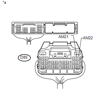
(a) Disconnect the D89 power management control ECU connector. |
|
(b) Measure the voltage according to the value(s) in the table below.
Standard Voltage:
|
Tester Connection |
Condition |
Specified Condition |
|---|---|---|
|
D89-2 (AM21) - Body ground |
Always |
9.5 to 14 V |
|
D89-1 (AM22) - Body ground |
Text in Illustration
|
*a |
Rear view of wire harness connector (to Power Management Control ECU) |
| NG |

|
REPAIR OR REPLACE HARNESS OR CONNECTOR IN CIRCUIT CONNECTED TO POWER SOURCE |
|

|
2. |
CHECK HARNESS AND CONNECTOR (POWER MANAGEMENT CONTROL ECU - BODY GROUND) |
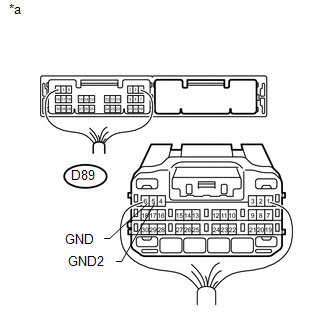
(a) Disconnect the D89 power management control ECU connector.
|
(b) Measure the resistance according to the value(s) in the table below. Standard Resistance:
Text in Illustration
|
|
| NG |
|
REPAIR OR REPLACE HARNESS OR CONNECTOR |
|
|
3. |
INSPECT POWER MANAGEMENT CONTROL ECU |
(a) Connect the power management control ECU connectors.
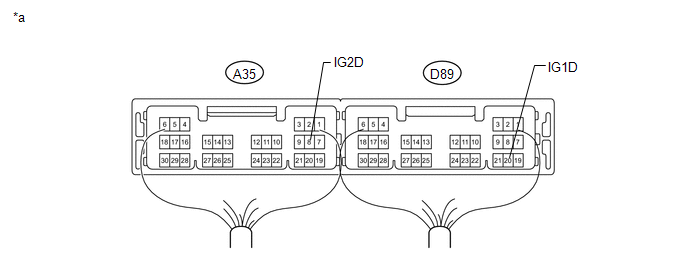
Text in Illustration
|
*a |
Component with harness connected (Power Management Control ECU) |
- |
- |
(b) Measure the voltage according to the value(s) in the table below.
Standard Voltage:
|
Tester Connection |
Switch Condition |
Specified Condition |
|---|---|---|
|
A35-8 (IG2D) - Body ground |
Engine switch off |
1 V or less |
|
Engine switch on (IG)* |
9 V or higher |
|
|
D89-20 (IG1D) - Body ground |
Engine switch off |
1 V or less |
|
Engine switch on (IG)* |
9 V or higher |
- *: To turn the engine switch on (IG), carry the key and press the engine switch twice with the shift lever in P and the brake pedal released.
| OK |
|
SYSTEM RETURNED TO NORMAL (DTC STORED DUE TO BAD CONNECTION, BUT SYSTEM RETURNED TO NORMAL BY RECONNECTING CONNECTOR) |
| NG |
|
REPLACE POWER MANAGEMENT CONTROL ECU (See page
|
|
|
|