| Last Modified: 08-28-2024 | 6.11:8.1.0 | Doc ID: RM100000000VJJ8 |
| Model Year Start: 2016 | Model: Sienna | Prod Date Range: [12/2015 - ] |
| Title: THEFT DETERRENT / KEYLESS ENTRY: SMART KEY SYSTEM(for Start Function): TERMINALS OF ECU; 2016 - 2020 MY Sienna [12/2015 - ] | ||
TERMINALS OF ECU
1. CHECK POWER MANAGEMENT CONTROL ECU
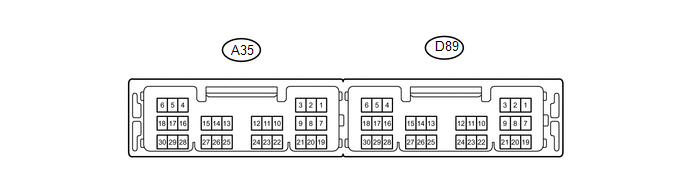
(a) Disconnect the A35 and D89 connectors.
(b) Measure the voltage and resistance according to the value(s) in the table below.
|
Terminal No. (Symbol) |
Wiring Color |
Terminal Description |
Condition |
Specified Condition |
|---|---|---|---|---|
|
A35-2 (STA) - Body ground |
SB - Body ground |
Starter relay operation signal |
Always |
93.8 to 136.4 Ω |
|
A35-3 (STAR) - Body ground |
P - Body ground |
Park neutral position switch signal |
Shift lever in P or N |
93.8 to 136.4 Ω |
|
A35-3 (STAR) - Body ground |
P - Body ground |
Park neutral position switch signal |
Shift lever in except P or N |
10 kΩ or higher |
|
A35-8 (IG2D) - Body ground |
P - Body ground |
IG2 relay operation signal |
Always |
131 to 387 Ω |
|
A35-11 (STP1) - Body ground |
L - Body ground |
Stop light switch signal |
Brake pedal depressed |
11 to 14 V |
|
A35-11 (STP1) - Body ground |
L - Body ground |
Stop light switch signal |
Brake pedal released |
Below 1 V |
|
D89-1 (AM22) - Body ground |
R - Body ground |
+B power supply |
Always |
9.5 to 14 V |
|
D89-2 (AM21) - Body ground |
R - Body ground |
+B power supply |
Always |
9.5 to 14 V |
|
D89-3 (SLP) - Body ground |
G - Body ground |
Steering lock actuator position signal |
Always |
10 kΩ or higher |
|
D89-5 (GND2) - Body ground |
W-B - Body ground |
Ground |
Always |
Below 1 Ω |
|
D89-6 (GND) - Body ground |
W-B - Body ground |
Ground |
Always |
Below 1 Ω |
|
D89-8 (SLR+) - Body ground |
Y - Body ground |
Steering lock motor signal |
Always |
10 kΩ or higher |
|
D89-11 (CA3N) - Body ground |
W - Body ground |
CAN communication line |
Always |
10 kΩ or higher |
|
D89-12 (CA3P) - Body ground |
G - Body ground |
CAN communication line |
Always |
10 kΩ or higher |
|
D89-13 (CA1L) - Body ground |
W - Body ground |
CAN communication line |
Always |
10 kΩ or higher |
|
D89-14 (CA1H) - Body ground |
LG - Body ground |
CAN communication line |
Always |
10 kΩ or higher |
|
D89-17 (SSW2) - Body ground |
B - Body ground |
Engine switch signal |
Engine switch pushed |
Below 1 Ω |
|
D89-17 (SSW2) - Body ground |
B - Body ground |
Engine switch signal |
Engine switch not pushed |
10 kΩ or higher |
|
D89-18 (SSW1) - Body ground |
L - Body ground |
Engine switch signal |
Engine switch pushed |
Below 1 Ω |
|
D89-18 (SSW1) - Body ground |
L - Body ground |
Engine switch signal |
Engine switch not pushed |
10 kΩ or higher |
|
D89-20 (IG1D) - Body ground |
Y - Body ground |
IG1 relay operation signal |
Always |
50.63 to 123.75 Ω |
|
D89-24 (LIN2) - Body ground |
Y - Body ground |
LIN communication line |
Always |
10 kΩ or higher |
If the result is not as specified, there may be a malfunction on the wire harness side.
(c) Reconnect the A35 and D89 connectors.
(d) Measure the voltage and check pulses according to the value(s) in the table below.
|
Terminal No. (Symbol) |
Wiring Color |
Terminal Description |
Condition |
Specified Condition |
|---|---|---|---|---|
|
A35-4 (NE) - D89-6 (GND) |
G - W-B |
Crankshaft position sensor signal |
Idling with warm engine |
Pulse generation (See waveform 1) |
|
A35-8 (IG2D) - D89-6 (GND) |
P - W-B |
IG2 signal |
Engine switch on (IG) |
9 V or higher |
|
A35-8 (IG2D) - D89-6 (GND) |
P - W-B |
IG2 signal |
Engine switch on (ACC) |
1 V or less |
|
D89-3 (SLP) - D89-6 (GND) |
G - W-B |
Steering lock actuator signal |
Steering lock released |
Pulse generation (See waveform 2) |
|
D89-3 (SLP) - D89-6 (GND) |
G - W-B |
Steering lock actuator signal |
Shift lever in P Steering lock locked |
Pulse generation (See waveform 2) |
|
D89-8 (SLR+) - D89-6 (GND) |
Y - W-B |
Steering motor signal |
Steering lock motor operating |
Pulse generation (See waveform 3) |
|
D89-8 (SLR+) - D89-6 (GND) |
Y - W-B |
Steering motor signal |
Steering lock motor not operating |
Pulse generation (See waveform 3) |
|
D89-10 (INDW) - D89-6 (GND) |
G - W-B |
Warning signal |
Brake pedal depressed, shift lever in P, engine switch on (ACC, IG) |
8 to 14 V |
|
D89-16 (P) - D89-6 (GND) |
R - W-B |
Shift lock signal |
Shift lever in P |
8 to 14 V |
|
D89-16 (P) - D89-6 (GND) |
R - W-B |
Shift lock signal |
Shift lever not in P |
1.5 V or less |
|
D89-17 (SSW2) - D89-6 (GND) |
B - W-B |
Engine switch signal |
Engine switch not pushed |
9 V or higher |
|
D89-17 (SSW2) - D89-6 (GND) |
B - W-B |
Engine switch signal |
Engine switch pushed |
1 V or less |
|
D89-18 (SSW1) - D89-6 (GND) |
L - W-B |
Engine switch signal |
Engine switch not pushed |
9 V or higher |
|
D89-18 (SSW1) - D89-6 (GND) |
L - W-B |
Engine switch signal |
Engine switch pushed |
1 V or less |
|
D89-19 (ACCD) - D89-6 (GND) |
L - W-B |
ACC signal |
Engine switch on (ACC) |
8.5 V or higher |
|
D89-19 (ACCD) - D89-6 (GND) |
L - W-B |
ACC signal |
Engine switch off |
1 V or less |
|
D89-20 (IG1D) - D89-6 (GND) |
Y - W-B |
IG1 signal |
Engine switch on (IG) |
9 V or higher |
|
D89-20 (IG1D) - D89-6 (GND) |
Y - W-B |
IG1 signal |
Engine switch on (ACC) |
1 V or less |
|
D89-22 (INDS) - D89-6 (GND) |
Y - W-B |
Vehicle condition signal |
Brake pedal depressed, shift lever in P |
8 to 14 V |
|
D89-23 (SPD) - D89-6 (GND) |
LG - W-B |
Vehicle speed signal |
Engine switch on (IG), wheel rotated slowly |
Pulse generation (See waveform 4) |
If the result is not as specified, the ECU may have a malfunction.
(e) Using an oscilloscope, check the signal waveform of the ECU.
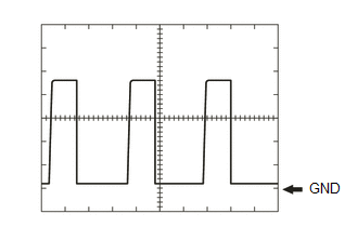
(1) Waveform 1
|
Tester Connection |
A35-4 (NE) - D89-6 (GND) |
|
Tool Setting |
1 V/DIV., 2 ms./DIV. |
|
Vehicle Condition |
Idling with warm engine |
HINT:
The wavelength becomes shorter as the engine speed increases.
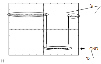
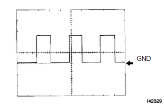
(2) Waveform 2
|
Tester Connection |
D89-3 (SLP) - D89-6 (GND) |
|
Tool Setting |
2 V/DIV., 100 ms./DIV. |
|
Vehicle Condition |
Steering lock/unlock |
Text in Illustration
|
*a |
Lock |
|
*b |
Unlock |
|
*c |
GND |
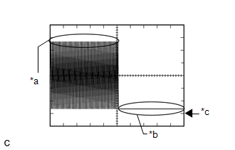
(3) Waveform 3
|
Tester Connection |
D89-8 (SLR+) - D89-6 (GND) |
|
Tool Setting |
2 V/DIV., 200 ms./DIV. |
|
Vehicle Condition |
Steering lock motor not operating → Steering lock motor operating → Steering lock motor not operating |
Text in Illustration
|
*a |
Steering lock motor not operating |
|
*b |
Steering lock motor operating |
(4) Waveform 4
|
Tester Connection |
D89-23 (SPD) - D89-6 (GND) |
|
Tool Setting |
5 V/DIV., 10 ms./DIV. |
|
Vehicle Condition |
Driving at approx. 20 km/h (12 mph) |
HINT:
The wavelength becomes shorter as the vehicle speed increases.
2. CHECK CERTIFICATION ECU (SMART KEY ECU ASSEMBLY)
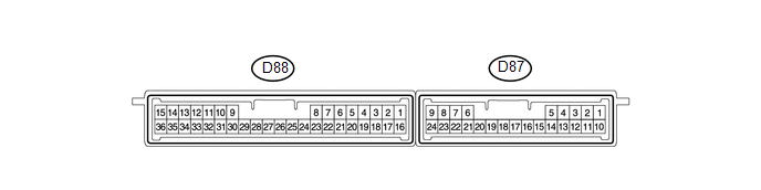
(a) Disconnect the D88 connector.
(b) Measure the voltage and resistance according to the value(s) in the table below.
|
Terminal No. (Symbol) |
Wiring Color |
Terminal Description |
Condition |
Specified Condition |
|---|---|---|---|---|
|
D88-1 (+B) - Body ground |
G - Body ground |
+B power supply |
Always |
11 to 14 V |
|
D88-11 (SWIL) - Body ground |
SB - Body ground |
Illumination signal |
Light control switch tail or head |
8 to 14 V |
|
D88-15 (E)- Body ground |
W-B - Body ground |
Ground |
Always |
Below 1 Ω |
|
D88-16 (IG) - Body ground |
B - Body ground |
IG power supply |
Engine switch on (IG) |
11 to 14 V |
|
D88-29 (LIN) - Body ground |
Y - Body ground |
LIN communication line |
Always |
10 kΩ or higher |
If the result is not as specified, there may be a malfunction on the wire harness side.
(c) Reconnect the D88 connector.
(d) Measure the voltage according to the value(s) in the table below.
|
Terminal No. (Symbol) |
Wiring Color |
Terminal Description |
Condition |
Specified Condition |
|---|---|---|---|---|
|
D88-11 (SWIL) - Body ground |
SB - Body ground |
Illumination signal |
Light control switch tail or head |
8 to 14 V |
If the result is not as specified, the ECU may have a malfunction.
3. CHECK STEERING LOCK ACTUATOR ASSEMBLY (STEERING LOCK ECU)

(a) Disconnect the D29 connector.
(b) Measure the voltage and resistance according to the value(s) in the table below.
|
Terminal No. (Symbol) |
Wiring Color |
Terminal Description |
Condition |
Specified Condition |
|---|---|---|---|---|
|
D29-1 (GND) - Body ground |
W-B - Body ground |
Ground |
Always |
Below 1 Ω |
|
D29-6 (IG2) - Body ground |
B - Body ground |
Ignition power supply |
Engine switch on (IG) |
11 to 14 V |
|
D29-6 (IG2) - Body ground |
B - Body ground |
Ignition power supply |
Engine switch off |
Below 1 V |
|
D29-7 (B) - Body ground |
R - Body ground |
+B power supply |
Always |
11 to 14 V |
- If the result is not as specified, there may be a malfunction on the wire harness side.
(c) Reconnect the D29 connector.
(d) Measure the voltage according to the value(s) in the table below.
|
Terminal No. (Symbol) |
Wiring Color |
Terminal Description |
Condition |
Specified Condition |
|---|---|---|---|---|
|
D29-4 (SLP1) - D29-1 (GND) |
G - W-B |
Steering lock actuator position signal |
Steering locked |
11 to 14 V |
|
D29-4 (SLP1) - D29-1 (GND) |
G - W-B |
Steering lock actuator position signal |
Steering released |
Below 1 V |
- If the result is not as specified, the ECU may have a malfunction.
|
|
|