| Last Modified: 08-28-2024 | 6.11:8.1.0 | Doc ID: RM100000000VJH2 |
| Model Year Start: 2016 | Model: Sienna | Prod Date Range: [12/2015 - ] |
| Title: DOOR LOCK: WIRELESS DOOR LOCK CONTROL SYSTEM(w/ Smart Key System): No Answer-Back; 2016 - 2020 MY Sienna [12/2015 - ] | ||
|
No Answer-Back |
DESCRIPTION
In some cases, wireless door lock control functions are normal but the hazard warning light and/or wireless door lock buzzer answer-back function(s) does not operate. In such cases, the main body ECU hazard warning light and wireless door lock buzzer signal outputs may be malfunctioning.
NOTICE:
Troubleshooting should be started after confirming that the customize status of the answer-back function has been switched ON.
WIRING DIAGRAM
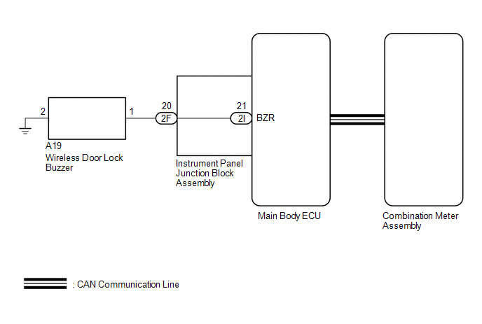
CAUTION / NOTICE / HINT
NOTICE:
Before performing the inspection, check that there are no problems related to the CAN communication system.
PROCEDURE
|
1. |
READ VALUE USING TECHSTREAM (DOOR LOCK POSITION SWITCH) |
(a) Connect the Techstream to the DLC3.
(b) Turn the engine switch on (IG).
(c) Turn the Techstream on.
(d) Enter the following menus: Body Electrical / Main Body / Data List.
(e) Read the Data List according to the display on the Techstream.
Main Body (Main Body ECU)
|
Tester Display |
Measurement Item/Range |
Normal Condition |
Diagnostic Note |
|---|---|---|---|
|
FR Door Lock Pos |
Front RH side door lock position switch signal / UNLOCK or LOCK |
UNLOCK: Front RH side door unlocked LOCK: Front RH side door locked |
- |
|
FL Door Lock Pos |
Front LH side door lock position switch signal / UNLOCK or LOCK |
UNLOCK: Front LH side door unlocked LOCK: Front LH side door locked |
- |
|
RR-Door Lock Pos SW |
Rear RH side door lock position switch signal / ON or OFF |
ON: Rear RH side rear door unlocked OFF: Rear RH side rear door locked |
- |
|
RL-Door Lock Pos SW |
Rear LH side door lock position switch signal / ON or OFF |
ON: Rear LH side rear door unlocked OFF: Rear LH side rear door locked |
- |
OK:
The Techstream should display as shown in the table according to door lock operation.
| NG |

|
GO TO LIGHTING SYSTEM (Proceed to Door Unlock Detection Switch Circuit) |
|

|
2. |
CHECK WIRELESS DOOR LOCK CONTROL FUNCTION |
(a) Check the wireless door lock control functions by operating the transmitter switch.
Result
|
Result |
Proceed to |
|---|---|
|
Wireless door lock functions are normal but hazard warning lights answer-back does not occur |
A |
|
Wireless door lock functions are normal but wireless door lock buzzer answer-back does not occur |
B |
|
Doors cannot be locked and unlocked with transmitter |
C |
| B |
|
| C |
|
|
|
3. |
CHECK HAZARD WARNING LIGHT |
(a) Select the Active Test, use the Techstream to generate a control command, and then check that the hazard warning lights flash.
OK:
Hazard warning lights flash continuously.
| OK |
|
| NG |
|
|
4. |
PERFORM ACTIVE TEST USING TECHSTREAM (WIRELESS DOOR LOCK BUZZER) |
(a) Select the Active Test, use the Techstream to generate a control command, and then check that the wireless buzzer operates normally.
Main Body
|
Tester Display |
Test Part |
Control Range |
Diagnostic Note |
|---|---|---|---|
|
Wireless Buzzer |
Wireless Door Lock Buzzer |
ON/OFF |
- |
OK:
Wireless buzzer turns ON/OFF.
| OK |
|
|
|
5. |
CHECK HARNESS AND CONNECTOR (WIRELESS DOOR LOCK BUZZER - INSTRUMENT PANEL JUNCTION BLOCK ASSEMBLY AND BODY GROUND) |
(a) Disconnect the wireless door lock buzzer connector.
(b) Disconnect the instrument panel junction block assembly connector.
(c) Measure the resistance according to the value(s) in the table below.
Standard Resistance:
|
Tester Connection |
Condition |
Specified Condition |
|---|---|---|
|
A19-2 - 2F-20 (BZR) |
Always |
Below 1 Ω |
|
A19-1 - Body ground |
Always |
|
|
A19-2 or 2F-20 (BZR) - Body ground |
Always |
10 kΩ or higher |
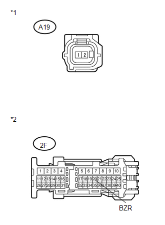
Text in Illustration
|
*a |
Front view of wire harness connector (to Wireless Door Lock Buzzer) |
|
*b |
Front view of wire harness connector (to Instrument Panel Junction Block Assembly) |
(d) Reconnect the wireless door lock buzzer and instrument panel junction block assembly connector.
| NG |
|
REPAIR OR REPLACE HARNESS OR CONNECTOR |
|
|
6. |
CHECK INSTRUMENT PANEL JUNCTION BLOCK ASSEMBLY |
(a) Remove the instrument panel junction block assembly (See page
![2016 - 2020 MY Sienna [12/2015 - ]; POWER DISTRIBUTION: MAIN BODY ECU: REMOVAL](/t3Portal/stylegraphics/info.gif) ).
).
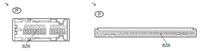
Text in Illustration
|
*a |
Component without harness connected (Instrument Panel Junction Block Assembly) |
- |
- |
(b) Measure the resistance according to the value(s) in the table below.
Standard Resistance:
|
Tester Connection |
Condition |
Specified Condition |
|---|---|---|
|
2F-20 (BZR) - 2I-21 (BZR) |
Always |
Below 1 Ω |
| NG |
|
|
|
7. |
REPLACE WIRELESS DOOR LOCK BUZZER |
(a) Temporarily replace the wireless door lock buzzer with a new or normally functioning one (See page
).
|
|
8. |
INSPECT WIRELESS DOOR LOCK BUZZER OPERATION |
(a) Check the operation of the wireless answer-back function.
OK:
Wireless answer-back function operation normally.
| OK |
|
END (WIRELESS DOOR LOCK BUZZER IS DEFECTIVE) |
| NG |
|
|
|
|