| Last Modified: 08-28-2024 | 6.11:8.1.0 | Doc ID: RM100000000VJGI |
| Model Year Start: 2016 | Model: Sienna | Prod Date Range: [12/2015 - ] |
| Title: DOOR LOCK: POWER DOOR LOCK CONTROL SYSTEM: All Doors LOCK/UNLOCK Functions do not Operate Via Door Control Switch; 2016 - 2020 MY Sienna [12/2015 - ] | ||
|
All Doors LOCK/UNLOCK Functions do not Operate Via Door Control Switch |
DESCRIPTION
The main body ECU receives switch signals from the door control switch and activates the door lock motor on each door according to these signals.
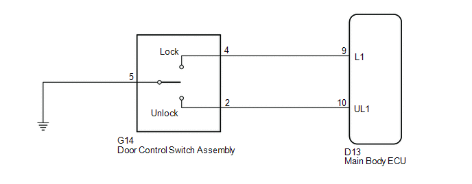
WIRING DIAGRAM
PROCEDURE
|
1. |
READ VALUE USING TECHSTREAM (DOOR CONTROL SWITCH) |
(a) Connect the Techstream to the DLC3.
(b) Turn the ignition switch to ON.
(c) Turn the Techstream on.
(d) Enter the following menus: Body Electrical / Main Body / Data List.
(e) Read the Data List according to the display on the Techstream.
Main Body
|
Tester Display |
Measurement Item/Range |
Normal Condition |
Diagnostic Note |
|---|---|---|---|
|
Door Lock SW-Lock |
Front passenger side door control switch lock signal/ON or OFF |
ON: Front passenger side door control switch pushed to lock position OFF: Front passenger side door control switch not pushed to lock position |
- |
|
Door Lock SW-Unlock |
Front passenger side door control switch unlock signal/ON or OFF |
ON: Front passenger side door control switch pushed to unlock position OFF: Front passenger side door control switch not pushed to unlock position |
- |
OK:
The Techstream indicates ON or OFF according to the switch operation shown in the table.
| OK |

|
|

|
2. |
INSPECT DOOR CONTROL SWITCH ASSEMBLY |
|
(a) Remove the door control switch assembly (See page
|
|
![2016 - 2020 MY Sienna [12/2015 - ]; DOOR LOCK: DOOR CONTROL SWITCH: REMOVAL](/t3Portal/stylegraphics/info.gif)
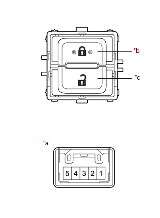
(b) Measure the resistance according to the value(s) in the table below.
Standard Resistance:
|
Tester Connection |
Switch Condition |
Specified Condition |
|---|---|---|
|
4 - 5 |
Locked |
Below 1 Ω |
|
4 - 5 |
off |
10 kΩ or higher |
|
2 - 5 |
Unlocked |
Below 1 Ω |
|
2 - 5 |
off |
10 kΩ or higher |
Text in Illustration
|
*a |
Component without harness connected (Door Control Switch Assembly) |
|
*b |
Lock |
|
*c |
Unlock |
| NG |
|
|
|
3. |
CHECK HARNESS AND CONNECTOR (DOOR CONTROL SWITCH ASSEMBLY - MAIN BODY ECU) |
(a) Disconnect the G14 door control switch assembly connector.
(b) Disconnect the D13 main body ECU connector.
(c) Measure the resistance according to the value(s) in the table below.
Standard Resistance:
|
Tester Connection |
Condition |
Specified Condition |
|---|---|---|
|
G14-2 - D13-10 (UL1) |
Always |
Below 1 Ω |
|
G14-4 - D13-9 (L1) |
Always |
Below 1 Ω |
|
G14-5 - Body ground |
Always |
Below 1 Ω |
|
G14-2 - Body ground |
Always |
10 kΩ or higher |
|
G6-4 - Body ground |
Always |
10 kΩ or higher |
| OK |
|
| NG |
|
REPAIR OR REPLACE HARNESS OR CONNECTOR |
|
|
|