| Last Modified: 08-28-2024 | 6.11:8.1.0 | Doc ID: RM100000000VJFT |
| Model Year Start: 2016 | Model: Sienna | Prod Date Range: [12/2015 - ] |
| Title: DOOR LOCK: SLIDE DOOR LOCK: INSPECTION; 2016 - 2020 MY Sienna [12/2015 - ] | ||
INSPECTION
PROCEDURE
1. INSPECT SLIDE DOOR HANDLE ASSEMBLY LH (w/o Power Slide Door)
|
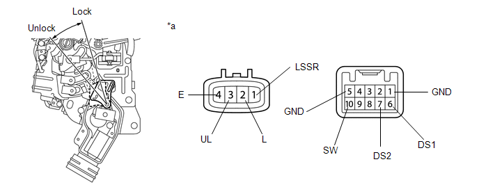
(a) Apply battery voltage to the motor terminals and check the operation of the slide door handle. Text in Illustration
OK:
If the result is not as specified, replace the slide door handle. |
|
(b) Measure the resistance according to the values in the table below.
Standard Resistance:
|
Tester Connection |
Condition |
Specified Condition |
|---|---|---|
|
1 (LSSR) - 4 (E) |
Locked |
10 kΩ or higher |
|
1 (LSSR) - 4 (E) |
Unlocked |
Below 1 Ω |
If the result is not as specified, replace the slide door handle.
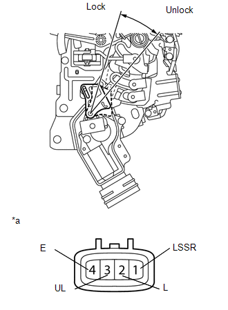
2. INSPECT SLIDE DOOR HANDLE ASSEMBLY LH (w/ Power Slide Door)
(a) Apply battery voltage to the motor terminals and check the operation of the slide door handle.

Text in Illustration
|
*a |
Component without harness connected (slide door handle LH) |
OK:
|
Measurement Condition |
Specified Condition |
|---|---|
|
Battery positive (+) → 2 (L) Battery negative (-) → 3 (UL) |
Locks |
|
Battery positive (+) → 3 (UL) Battery negative (-) → 2 (L) |
Unlocks |
If the result is not as specified, replace the slide door handle.
(b) Measure the resistance according to the values in the table below.
Standard Resistance:
|
Tester Connection |
Condition |
Specified Condition |
|---|---|---|
|
1 (LSSR) - 4 (E) |
Locked |
10 kΩ or higher |
|
1 (LSSR) - 4 (E) |
Unlocked |
Below 1 Ω |
If the result is not as specified, replace the slide door handle.
(c) Measure the resistance according to the values in the table below.
Standard Resistance:
|
Tester Connection |
Condition |
Specified Condition |
|---|---|---|
|
1 (GND) - 4 (DS2) |
Inner Handle Pulled |
Below 1 Ω |
|
1 (GND) - 3 (DS1) |
||
|
1 (GND) - 4 (DS2) |
Inner Handle not Pulled |
10 kΩ or higher |
|
1 (GND) - 3 (DS1) |
If the result is not as specified, replace the slide door handle.
3. INSPECT SLIDE DOOR HANDLE ASSEMBLY LH (w/ Smart Key System)
(a) Apply battery voltage to the motor terminals and check the operation of the slide door handle.
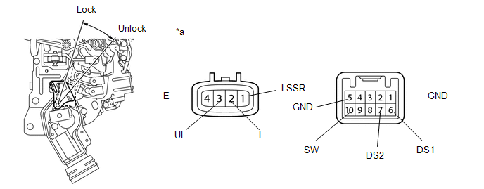
Text in Illustration
|
*a |
Component without harness connected (slide door handle LH) |
OK:
|
Measurement Condition |
Specified Condition |
|---|---|
|
Battery positive (+) → 2 (L) Battery negative (-) → 3 (UL) |
Locks |
|
Battery positive (+) → 3 (UL) Battery negative (-) → 2 (L) |
Unlocks |
If the result is not as specified, replace the slide door handle.
(b) Measure the resistance according to the values in the table below.
Standard Resistance:
|
Tester Connection |
Condition |
Specified Condition |
|---|---|---|
|
1 (LSSR) - 4 (E) |
Locked |
10 kΩ or higher |
|
1 (LSSR) - 4 (E) |
Unlocked |
Below 1 Ω |
If the result is not as specified, replace the slide door handle.
(c) Measure the resistance according to the values in the table below.
Standard Resistance:
|
Tester Connection |
Condition |
Specified Condition |
|---|---|---|
|
1 (GND) - 6 (DS1) |
Inner Handle Pulled |
Below 1 Ω |
|
1 (GND) - 7 (DS2) |
||
|
5 (GND) - 10 (SW) |
||
|
1 (GND) - 6 (DS1) |
Inner Handle not Pulled |
10 kΩ or higher |
|
1 (GND) - 7 (DS2) |
||
|
5 (GND) - 10 (SW) |
If the result is not as specified, replace the slide door handle.
4. INSPECT SLIDE DOOR HANDLE ASSEMBLY RH (w/o Power Slide Door)
|
(a) Apply battery voltage to the motor terminals and check the operation of the slide door handle. Text in Illustration
OK:
If the result is not as specified, replace the slide door handle. |
|
(b) Measure the resistance according to the values in the table below.
Standard Resistance:
|
Tester Connection |
Condition |
Specified Condition |
|---|---|---|
|
1 (LSSR) - 4 (E) |
Locked |
10 kΩ or higher |
|
1 (LSSR) - 4 (E) |
Unlocked |
Below 1 Ω |
If the result is not as specified, replace the slide door handle.
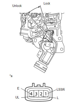
5. INSPECT SLIDE DOOR HANDLE ASSEMBLY RH (w/ Power Slide Door)
(a) Apply battery voltage to the motor terminals and check the operation of the door lock motor.
Text in Illustration
|
*a |
Component without harness connected (slide door handle RH) |
OK:
|
Measurement Condition |
Specified Condition |
|---|---|
|
Battery positive (+) → 2 (L) Battery negative (-) → 3 (UL) |
Locks |
|
Battery positive (+) → 3 (UL) Battery negative (-) → 2 (L) |
Unlocks |
If the result is not as specified, replace the slide door handle.
(b) Measure the resistance according to the values in the table below.
Standard Resistance:
|
Tester Connection |
Condition |
Specified Condition |
|---|---|---|
|
1 (LSSR) - 4 (E) |
Locked |
10 kΩ or higher |
|
1 (LSSR) - 4 (E) |
Unlocked |
Below 1 Ω |
If the result is not as specified, replace the slide door handle.
(c) Measure the resistance according to the values in the table below.
Standard Resistance:
|
Tester Connection |
Condition |
Specified Condition |
|---|---|---|
|
1 (GND) - 4 (DS2) |
Inner Handle Pulled |
Below 1 Ω |
|
1 (GND) - 3 (DS1) |
||
|
1 (GND) - 4 (DS2) |
Inner Handle not Pulled |
10 kΩ or higher |
|
1 (GND) - 3 (DS1) |
If the result is not as specified, replace the slide door handle.
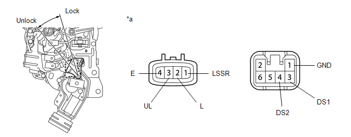
6. INSPECT SLIDE DOOR HANDLE ASSEMBLY RH (w/ Smart Key System)
(a) Apply battery voltage to the motor terminals and check the operation of the door lock motor.
Text in Illustration
|
*a |
Component without harness connected (slide door handle RH) |
OK:
|
Measurement Condition |
Specified Condition |
|---|---|
|
Battery positive (+) → 2 (L) Battery negative (-) → 3 (UL) |
Locks |
|
Battery positive (+) → 3 (UL) Battery negative (-) → 2 (L) |
Unlocks |
If the result is not as specified, replace the slide door handle.
(b) Measure the resistance according to the values in the table below.
Standard Resistance:
|
Tester Connection |
Condition |
Specified Condition |
|---|---|---|
|
1 (LSSR) - 4 (E) |
Locked |
10 kΩ or higher |
|
1 (LSSR) - 4 (E) |
Unlocked |
Below 1 Ω |
If the result is not as specified, replace the slide door handle.
(c) Measure the resistance according to the values in the table below.
Standard Resistance:
|
Tester Connection |
Condition |
Specified Condition |
|---|---|---|
|
1 (GND) - 6 (DS1) |
Inner Handle Pulled |
Below 1 Ω |
|
1 (GND) - 7 (DS2) |
||
|
5 (GND) - 10 (SW) |
||
|
1 (GND) - 6 (DS1) |
Inner Handle not Pulled |
10 kΩ or higher |
|
1 (GND) - 7 (DS2) |
||
|
5 (GND) - 10 (SW) |
If the result is not as specified, replace the slide door handle.
7. INSPECT POWER SLIDE DOOR LOCK ASSEMBLY LH
|
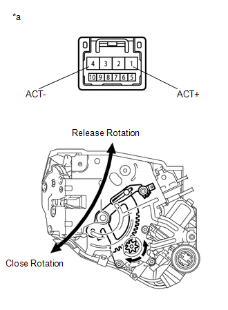
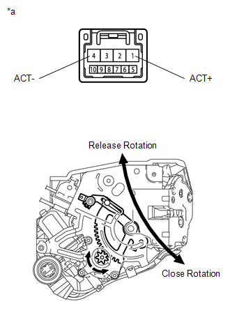
(a) Check the operation of the slide door closer motor. Text in Illustration
OK:
If the result is not as specified, replace the power slide door lock. |
|
|
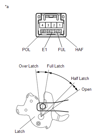
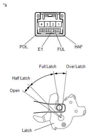
(b) Measure the resistance according to the values in the table below. Text in Illustration
Standard Resistance: Full Latch Switch
Half Latch Switch
Pawl Switch
|
|
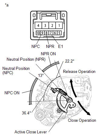
(c) Measure the resistance according to the values in the table below.
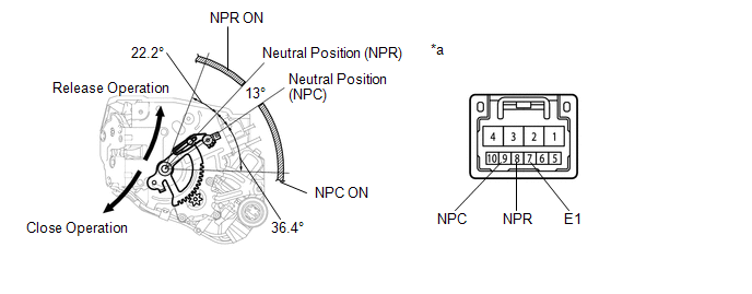
Text in Illustration
|
*a |
Component without harness connected (Power Slide Door Lock Assembly LH) |
Standard Resistance:
Neutral Position Switch (NPR)
|
Tester Connection |
Condition |
Specified Condition |
|---|---|---|
|
7 (E1) - 8 (NPR) |
Neutral Position (NPR) |
10 kΩ or higher |
|
Neutral Position (NPC) |
||
|
Active lever moved to release operation side |
Below 1 Ω |
|
|
Active lever moved to close operation side |
10 kΩ or higher |
Neutral Position Switch (NPC)
|
Tester Connection |
Condition |
Specified Condition |
|---|---|---|
|
7 (E1) - 9 (NPC) |
Neutral Position (NPR) |
10 kΩ or higher |
|
Neutral Position (NPC) |
||
|
Active lever moved to release operation side |
Below 1 Ω |
|
|
Active lever moved to close operation side |
10 kΩ or higher |
If the result is not as specified, replace the power slide door lock.
8. INSPECT POWER SLIDE DOOR LOCK ASSEMBLY RH
|
(a) Check the operation of the slide door closer motor. Text in Illustration
OK:
If the result is not as specified, replace the power slide door lock. |
|
|
(b) Measure the resistance according to the values in the table below. Text in Illustration
Standard Resistance: Full Latch Switch
Half Latch Switch
Pawl Switch
|
|
|
(c) Measure the resistance according to the values in the table below. Text in Illustration
Standard Resistance: Neutral Position Switch (NPR)
Neutral Position Switch (NPC)
If the result is not as specified, replace the power slide door lock. |
|
|
|
|