- Inner rear view mirror assembly
- Harness or connector
- AFS ECU (headlight swivel computer assembly)
| Last Modified: 08-28-2024 | 6.11:8.1.0 | Doc ID: RM100000000VJF9 |
| Model Year Start: 2016 | Model: Sienna | Prod Date Range: [12/2015 - 11/2017] |
| Title: NETWORKING: LIN COMMUNICATION SYSTEM: B2432; Lost Communication with Automatic High Beam Sensor; 2016 - 2017 MY Sienna [12/2015 - 11/2017] | ||
|
DTC |
B2432 |
Lost Communication with Automatic High Beam Sensor |
DESCRIPTION
The DTC is stored when the AFS ECU (headlight swivel computer assembly) detects malfunctions in the LIN communication system.
|
DTC Code |
DTC Detection Condition |
Trouble Area |
|---|---|---|
|
B2432 |
Malfunction in LIN communication system |
|
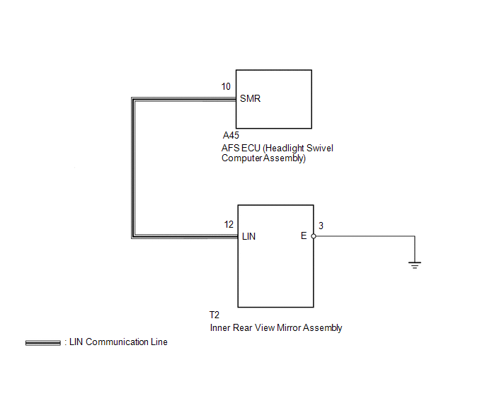
WIRING DIAGRAM
CAUTION / NOTICE / HINT
CAUTION:
Inspect the fuses for circuits related to this system before performing the following inspection procedure.
PROCEDURE
|
1. |
CLEAR DTC |
(a) Clear the DTCs (See page
![2016 - 2020 MY Sienna [12/2015 - ]; NETWORKING: LIN COMMUNICATION SYSTEM: DTC CHECK / CLEAR](/t3Portal/stylegraphics/info.gif) ).
).
|

|
2. |
CHECK FOR DTC |
(a) Check for DTCs (See page
).
Result
|
Result |
Proceed to |
|---|---|
|
DTC B2432 is output |
A |
|
DTC B2432 and B124D are output |
B |
|
No DTCs output |
C |
HINT:
When both B2432 and B124D are output at the same time, troubleshoot B124D first.
| B |

|
| C |
|
|
|
3. |
CHECK HARNESS AND CONNECTOR (AFS ECU (HEADLIGHT SWIVEL COMPUTER ASSEMBLY) - INNER REAR VIEW MIRROR ASSEMBLY) |
(a) Disconnect the A45 AFS ECU (headlight swivel computer assembly) connector
(b) Disconnect the T2 inner rear view mirror assembly connector.
(c) Measure the resistance according to the value(s) in the table below.
Standard Resistance (Check for Open):
|
Tester Connection |
Condition |
Specified Condition |
|---|---|---|
|
A45-10 (SMR) - T2-12 (LIN) |
Always |
Below 1 Ω |
Standard Resistance (Check for Short):
|
Tester Connection |
Condition |
Specified Condition |
|---|---|---|
|
T2-12 (LIN) - Body ground |
Always |
10 kΩ or higher |
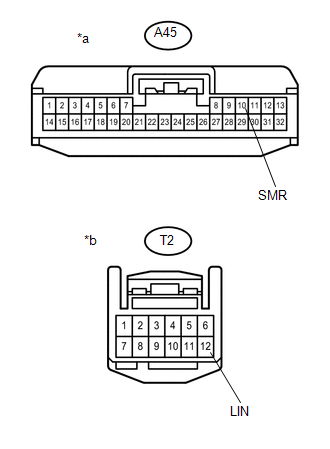
Text in Illustration
|
*a |
Front view of wire harness connector (to AFS ECU (Headlight Swivel Computer Assembly)) |
|
*b |
Front view of wire harness connector (to Inner Rear View Mirror Assembly) |
| NG |
|
REPAIR OR REPLACE HARNESS OR CONNECTOR |
|
|
4. |
INSPECT AFS ECU (HEADLIGHT SWIVEL ECU ASSEMBLY) |
(a) Reconnect the A45 AFS ECU (headlight swivel computer assembly) connector.
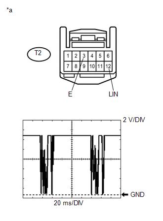
(b) Connect an oscilloscope to the T2 inner rear view mirror assembly connector.
|
(c) Check the waveform. OK:
Text in Illustration
|
|
| OK |
|
| NG |
|
|
|
|