| Last Modified: 08-28-2024 | 6.11:8.1.0 | Doc ID: RM100000000VJES |
| Model Year Start: 2016 | Model: Sienna | Prod Date Range: [12/2015 - 08/2016] |
| Title: NETWORKING: LIN COMMUNICATION SYSTEM: TERMINALS OF ECU; 2016 MY Sienna [12/2015 - 08/2016] | ||
TERMINALS OF ECU
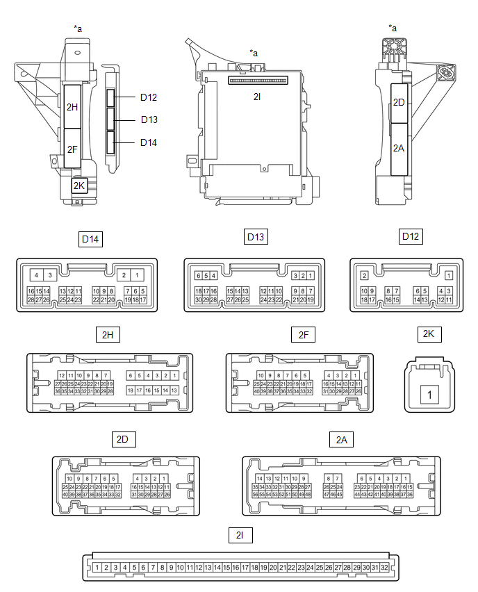
1. CHECK MAIN BODY ECU AND INSTRUMENT PANEL JUNCTION BLOCK ASSEMBLY
Text in Illustration
|
*a |
Component without harness connected (Instrument Panel Junction Block Assembly) |
*b |
Component without harness connected (Main Body ECU) |
(a) Check main body ECU and instrument panel junction block.
(1) Remove the main body ECU from the instrument panel junction block assembly (See page
![2016 - 2020 MY Sienna [12/2015 - ]; POWER DISTRIBUTION: MAIN BODY ECU: REMOVAL](/t3Portal/stylegraphics/info.gif) ).
).
(2) Reconnect the instrument panel junction block assembly connectors.
(3) Measure the resistance and voltage according to the value(s) in the table below.
HINT:
Measure the values on the wire harness side with the connector disconnected.
|
Terminal No. (Symbol) |
Wiring Color |
Terminal Description |
Condition |
Specified Condition |
|---|---|---|---|---|
|
2I-11 (GND1) - Body ground |
- |
Ground |
Always |
Below 1 Ω |
|
2I-29 (ACC) - Body ground |
- |
ACC power supply |
Ignition switch ACC |
11 to 14 V |
|
2I-30 (BECU) - Body ground |
- |
Battery power supply |
Always |
11 to 14 V |
|
2I-32 (IG) - Body ground |
- |
IG power supply |
Ignition switch ON |
11 to 14 V |
(4) Install the main body ECU to instrument panel junction block assembly.
(5) Measure the pulse according to the value(s) in the table below.
|
Terminal No. (Symbol) |
Wiring Color |
Terminal Description |
Condition |
Specified Condition |
|---|---|---|---|---|
|
2D-18 - Body ground |
G - Body ground |
LIN communication line |
Ignition switch ON |
Pulse generation |
|
2D-33 - Body ground |
L - Body ground |
LIN communication line |
Ignition switch ON |
Pulse generation |
|
2H-27 - Body ground |
L - Body ground |
LIN communication line |
Ignition switch ON |
Pulse generation |
2. CHECK MULTIPLEX NETWORK MASTER SWITCH ASSEMBLY

Text in Illustration
|
*a |
Component without harness connected (Multiplex Network Master Switch Assembly) |
- |
- |
(a) Check the multiplex network master switch assembly.
(1) Disconnect the H14 multiplex network master switch assembly connector.
(2) Measure the resistance and voltage according to the value(s) in the table below.
|
Terminal No. (Symbol) |
Wiring Color |
Terminal Description |
Condition |
Specified Condition |
|---|---|---|---|---|
|
H14-11 (B) - Body ground |
W - Body ground |
Battery power supply |
Always |
11 to 14 V |
|
H14-12 (GND) - Body ground |
W-B - Body ground |
Ground |
Always |
Below 1 Ω |
HINT:
If the result is not as specified, there may be a malfunction on the wire harness side.
(3) Reconnect the H14 multiplex network master switch assembly connector.
(4) Measure the pulse according to the value(s) in the table below.
|
Terminal No. (Symbol) |
Wiring Color |
Terminal Description |
Condition |
Specified Condition |
|---|---|---|---|---|
|
H14-16 (LIN2) - Body ground |
L - Body ground |
LIN communication line |
Ignition switch ON |
Pulse generation |
|
H14-17 (LIN1) - Body ground |
G - Body ground |
LIN communication line |
Ignition switch ON |
Pulse generation |
HINT:
If the result is not as specified, the multiplex network master switch assembly may have a malfunction.
3. CHECK FRONT POWER WINDOW REGULATOR MOTOR ASSEMBLY LH

Text in Illustration
|
*a |
Component without harness connected (Front Power Window Regulator Motor Assembly LH) |
- |
- |
(a) Check the front power window regulator motor assembly LH.
(1) Disconnect the H1 front power window regulator motor assembly LH connector.
(2) Measure the resistance and voltage according to the value(s) in the table below.
|
Terminal No. (Symbol) |
Wiring Color |
Terminal Description |
Condition |
Specified Condition |
|---|---|---|---|---|
|
H1-2 (B) - Body ground |
G - Body ground |
Battery power supply |
Always |
11 to 14 V |
|
H1-1 (GND) - Body ground |
W-B - Body ground |
Ground |
Always |
Below 1 Ω |
HINT:
If the result is not as specified, there may be a malfunction on the wire harness side.
(3) Reconnect the H1 front power window regulator motor assembly LH connector.
(4) Measure the pulse according to the value(s) in the table below.
|
Terminal No. (Symbol) |
Wiring Color |
Terminal Description |
Condition |
Specified Condition |
|---|---|---|---|---|
|
H1-9 (LIN) - Body ground |
L - Body ground |
LIN communication line |
Ignition switch ON |
Pulse generation |
HINT:
If the result is not as specified, the front power window regulator motor assembly LH may have a malfunction.
4. CHECK FRONT POWER WINDOW REGULATOR MOTOR ASSEMBLY RH

Text in Illustration
|
*a |
Component without harness connected (Front Power Window Regulator Motor Assembly RH) |
- |
- |
(a) Check the front power window regulator assembly RH.
(1) Disconnect the G1 front power window regulator motor assembly RH connector.
(2) Measure the resistance and voltage according to the value(s) in the table below.
|
Terminal No. (Symbol) |
Wiring Color |
Terminal Description |
Condition |
Specified Condition |
|---|---|---|---|---|
|
G1-2 (B) - Body ground |
G - Body ground |
Battery power supply |
Always |
11 to 14 V |
|
G1-1 (GND) - Body ground |
W-B - Body ground |
Ground |
Always |
Below 1 Ω |
HINT:
If the result is not as specified, there may be a malfunction on the wire harness side.
(3) Reconnect the G1 front power window regulator motor assembly RH connector.
(4) Measure the pulse according to the value(s) in the table below.
|
Terminal No. (Symbol) |
Wiring Color |
Terminal Description |
Condition |
Specified Condition |
|---|---|---|---|---|
|
G1-9 (LIN) - Body ground |
GR - Body ground |
LIN communication line |
Ignition switch ON |
Pulse generation |
HINT:
If the result is not as specified, the front power window regulator motor assembly RH may have a malfunction.
5. CHECK REAR POWER WINDOW REGULATOR MOTOR ASSEMBLY LH

Text in Illustration
|
*a |
Component without harness connected (Rear Power Window Regulator Motor Assembly LH) |
- |
- |
(a) Check the rear power window regulator motor assembly LH.
(1) Disconnect the J7 rear power window regulator motor assembly LH connector.
(2) Measure the resistance and voltage according to the value(s) in the table below.
|
Terminal No. (Symbol) |
Wiring Color |
Terminal Description |
Condition |
Specified Condition |
|---|---|---|---|---|
|
J7-2 (B) - Body ground |
GR - Body ground |
Battery power supply |
Always |
11 to 14 V |
|
J7-1 (GND) - Body ground |
W-B - Body ground |
Ground |
Always |
Below 1 Ω |
HINT:
If the result is not as specified, there may be a malfunction on the wire harness side.
(3) Reconnect the J7 rear power window regulator motor assembly LH connector.
(4) Measure the pulse according to the value(s) in the table below.
|
Terminal No. (Symbol) |
Wiring Color |
Terminal Description |
Condition |
Specified Condition |
|---|---|---|---|---|
|
J7-9 (LIN) - Body ground |
Y - Body ground |
LIN communication line |
Ignition switch ON |
Pulse generation |
HINT:
If the result is not as specified, the rear power window regulator motor assembly LH may have a malfunction.
6. CHECK REAR POWER WINDOW REGULATOR MOTOR ASSEMBLY RH

Text in Illustration
|
*a |
Component without harness connected (Rear Power Window Regulator Motor Assembly RH) |
- |
- |
(a) Check the rear power window regulator motor assembly RH.
(1) Disconnect the I7 rear power window regulator motor assembly RH connector.
(2) Measure the resistance and voltage according to the value(s) in the table below.
|
Terminal No. (Symbol) |
Wiring Color |
Terminal Description |
Condition |
Specified Condition |
|---|---|---|---|---|
|
I7-2 (B) - Body ground |
R - Body ground |
Battery power supply |
Always |
11 to 14 V |
|
I7-1 (GND) - Body ground |
W-B - Body ground |
Ground |
Always |
Below 1 Ω |
HINT:
If the result is not as specified, there may be a malfunction on the wire harness side.
(3) Reconnect the I7 rear power window regulator motor assembly RH connector.
(4) Measure the pulse according to the value(s) in the table below.
|
Terminal No. (Symbol) |
Wiring Color |
Terminal Description |
Condition |
Specified Condition |
|---|---|---|---|---|
|
I7-9 (LIN) - Body ground |
Y - Body ground |
LIN communication line |
Ignition switch ON |
Pulse generation |
HINT:
If the result is not as specified, the rear power window regulator motor assembly RH may have a malfunction.
7. CHECK AFS ECU (HEADLIGHT SWIVEL COMPUTER ASSEMBLY) (w/ HID Headlight System)

Text in Illustration
|
*a |
Component without harness connected (AFS ECU (headlight swivel computer assembly)) |
- |
- |
(a) Check the AFS ECU (headlight swivel computer assembly).
(1) Disconnect the A45 AFS ECU connector.
(2) Measure the resistance and voltage according to the value(s) in the table below.
|
Terminal No. (Symbol) |
Wiring Color |
Terminal Description |
Condition |
Specified Condition |
|---|---|---|---|---|
|
A45-15 (IG) - Body ground |
G - Body ground |
IG power supply |
Ignition switch ON |
11 to 14 V |
|
A45-22 (E1) - Body ground |
W-B - Body ground |
Ground |
Always |
Below 1 Ω |
HINT:
If the result is not as specified, there may be a malfunction on the wire harness side.
(3) Reconnected the A45 AFS ECU (headlight swivel computer assembly) connector.
(4) Measure the pulse according to the value(s) in the table below.
|
Terminal No. (Symbol) |
Wiring Color |
Terminal Description |
Condition |
Specified Condition |
|---|---|---|---|---|
|
A45-10 (SMR) - Body ground |
V - Body ground |
LIN communication line |
Ignition switch ON |
Pulse generation |
HINT:
If the result is not as specified, AFS ECU (headlight swivel computer assembly) may have a malfunction.
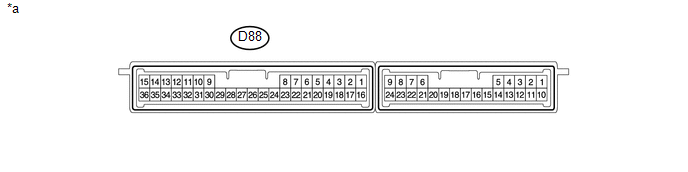
8. CHECK CERTIFICATION ECU (SMART KEY ECU) (w/ Smart Key System)
Text in Illustration
|
*a |
Component without harness connected (Certification ECU (Smart Key ECU)) |
- |
- |
(a) Check the certification ECU (smart key ECU).
(1) Disconnect the D88 certification ECU (smart key ECU) connector.
(2) Measure the resistance and voltage according to the value(s) in the table below.
|
Terminal No. (Symbol) |
Wiring Color |
Terminal Description |
Condition |
Specified Condition |
|---|---|---|---|---|
|
D88-1 (+B) - Body ground |
G - Body ground |
Battery power supply |
Always |
11 to 14 V |
|
D88-16 (IG) - Body ground |
B - Body ground |
IG power supply |
Ignition switch ON |
11 to 14 V |
|
D88-15 (E) - Body ground |
W-B - Body ground |
Ground |
Always |
Below 1 Ω |
HINT:
If the result is not as specified, there may be a malfunction on the wire harness side.
(3) Reconnect the D88 certification ECU (smart key ECU) connector.
(4) Measure the pulse according to the value(s) in the table below.
|
Terminal No. (Symbol) |
Wiring Color |
Terminal Description |
Condition |
Specified Condition |
|---|---|---|---|---|
|
D88-29 (LIN) - Body ground |
Y - Body ground |
LIN communication line |
Ignition switch ON |
Pulse generation |
HINT:
If the result is not as specified, the certification ECU (smart key ECU) may have a malfunction.
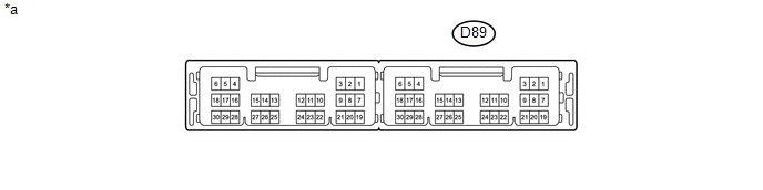
9. CHECK POWER MANAGEMENT CONTROL ECU
Text in Illustration
|
*a |
Component without harness connected (Power Management Control ECU) |
- |
- |
(a) Check the power management Control ECU.
(1) Disconnect the D89 power management control ECU connector.
(2) Measure the voltage and resistance according to the value(s) in the table below.
|
Terminal No. (Symbol) |
Wiring Color |
Terminal Description |
Condition |
Specified Condition |
|---|---|---|---|---|
|
D89-1 (AM22) - Body ground |
R - Body ground |
Battery power supply |
Always |
11 to 14 V |
|
D89-2 (AM21) - Body ground |
R - Body ground |
Battery power supply |
Always |
11 to 14 V |
|
D89-5 (GND2) - Body ground |
W-B - Body ground |
Ground |
Always |
Below 1 Ω |
|
D89-6 (GND) - Body ground |
W-B - Body ground |
Ground |
Always |
Below 1 Ω |
HINT:
If the result is not as specified, there may be a malfunction on the wire harness side.
(3) Reconnect the D89 power management control ECU connector.
(4) Measure the pulse according to the value(s) in the table below.
|
Terminal No. (Symbol) |
Wiring Color |
Terminal Description |
Condition |
Specified Condition |
|---|---|---|---|---|
|
D89-24 (LIN2) - Body ground |
Y - Body ground |
LIN communication line |
Ignition switch ON |
Pulse generation |
HINT:
If the result is not as specified, the power management control ECU may have a malfunction.
10. CHECK STEERING LOCK ACTUATOR ASSEMBLY

Text in Illustration
|
*a |
Component without harness connected (Steering Lock Actuator Assembly) |
- |
- |
(a) Check the steering lock actuator assembly.
(1) Disconnect the D29 steering lock actuator assembly connector.
(2) Measure the resistance and voltage according to the value(s) in the table below.
|
Terminal No. (Symbol) |
Wiring Color |
Terminal Description |
Condition |
Specified Condition |
|---|---|---|---|---|
|
D29-7 (B) - Body ground |
R - Body ground |
Battery power supply |
Always |
11 to 14 V |
|
D29-6 (IG2) - Body ground |
B - Body ground |
IG power supply |
Always |
11 to 14 V |
|
D29-1 (GND) - Body ground |
W-B - Body ground |
Ground |
Always |
Below 1 Ω |
HINT:
If the result is not as specified, there may be a malfunction on the wire harness side.
(3) Reconnect the D29 steering lock actuator assembly connector.
(4) Measure the pulse according to the value(s) in the table below.
|
Terminal No. (Symbol) |
Wiring Color |
Terminal Description |
Condition |
Specified Condition |
|---|---|---|---|---|
|
D29-5 (LIN) - Body ground |
Y - Body ground |
LIN communication line |
Ignition switch ON |
Pulse generation |
HINT:
If the result is not as specified, the steering lock actuator assembly may have a malfunction.
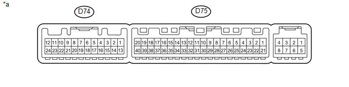
11. CHECK AIR CONDITIONING AMPLIFIER ASSEMBLY
Text in Illustration
|
*a |
Component without harness connected (Air Conditioning Amplifier Assembly) |
- |
- |
(a) Check the air conditioning amplifier assembly.
(1) Disconnect the D75 and D74 air conditioning amplifier assembly connectors.
(2) Measure the resistance and voltage according to the value(s) in the table below.
|
Terminal No. (Symbol) |
Wiring Color |
Terminal Description |
Condition |
Specified Condition |
|---|---|---|---|---|
|
D75-1 (IG+) - Body ground |
R - Body ground |
IG power supply |
Ignition switch off |
Below 1 V |
|
D75-21 (B) - Body ground |
P - Body ground |
Battery power supply |
Always |
11 to 14 V |
|
D74-24 (+B2) - Body ground |
P - Body ground |
Battery power supply |
Always |
11 to 14 V |
|
D75-14 (GND) - Body ground |
W-B - Body ground |
Ground |
Always |
Below 1 Ω |
|
D74-20 (GND2) - Body ground |
W-B - Body ground |
Ground |
Always |
Below 1 Ω |
HINT:
If the result is not as specified, there may be a malfunction on the wire harness side.
(3) Reconnect the D75 and D74 air conditioning amplifier assembly connectors.
(4) Measure the pulse according to the value(s) in the table below.
|
Terminal No. (Symbol) |
Wiring Color |
Terminal Description |
Condition |
Specified Condition |
|---|---|---|---|---|
|
D75-37 (LIN1) - Body ground |
LG - Body ground |
LIN communication line |
Ignition switch ON |
Pulse generation |
|
D74-13 (RLIN) - Body ground |
L - Body ground |
LIN communication line |
Ignition switch ON |
Pulse generation |
HINT:
If the result is not as specified, the air conditioning amplifier assembly may have a malfunction.
12. CHECK AIR CONDITIONING CONTROL ASSEMBLY

Text in Illustration
|
*a |
Component without harness connected (Air Conditioning Control Assembly) |
- |
- |
(a) Check the air conditioning control assembly.
(1) Disconnect the D69 air conditioning control assembly connector.
(2) Measure the resistance and voltage according to the value(s) in the table below.
|
Terminal No. (Symbol) |
Wiring Color |
Terminal Description |
Condition |
Specified Condition |
|---|---|---|---|---|
|
D69-4 (IG+) - Body ground |
R - Body ground |
IG power supply |
Ignition switch ON |
11 to 14 V |
|
D69-5 (GND) - Body ground |
W-B - Body ground |
Ground |
Always |
Below 1 Ω |
HINT:
If the result is not as specified, there may be a malfunction on the wire harness side.
(3) Reconnect the D69 air conditioning control assembly connector.
(4) Measure the pulse according to the value(s) in the table below.
|
Terminal No. (Symbol) |
Wiring Color |
Terminal Description |
Condition |
Specified Condition |
|---|---|---|---|---|
|
D69-8 (LIN1) - Body ground |
LG - Body ground |
LIN communication line |
Ignition switch ON |
Pulse generation |
HINT:
If the result is not as specified, the air conditioning control assembly may have a malfunction.
13. CHECK NO. 2 AIR CONDITIONING CONTROL ASSEMBLY

Text in Illustration
|
*a |
Component without harness connected (No. 2 Air Conditioning Control Assembly) |
- |
- |
(a) Check No. 2 air conditioning control assembly.
(1) Disconnect the T7 No. 2 air conditioning control assembly connector.
(2) Measure the resistance and voltage according to the value(s) in the table below.
|
Terminal No. (Symbol) |
Wiring Color |
Terminal Description |
Condition |
Specified Condition |
|---|---|---|---|---|
|
T7-1 (IG) - Body ground |
R - Body ground |
IG power supply |
Ignition switch ON |
11 to 14 V |
|
T7-4 (E) - Body ground |
W-B - Body ground |
Ground |
Always |
Below 1 Ω |
HINT:
If the result is not as specified, there may be a malfunction on the wire harness side.
(3) Reconnect the T7 No. 2 air conditioning control assembly connector.
(4) Measure the pulse according to the value(s) in the table below.
|
Terminal No. (Symbol) |
Wiring Color |
Terminal Description |
Condition |
Specified Condition |
|---|---|---|---|---|
|
T7-2 (RLIN) - Body ground |
L - Body ground |
LIN communication line |
Ignition switch ON |
Pulse generation |
HINT:
If the result is not as specified, the No. 2 air conditioning control assembly may have a malfunction.
|
|
|