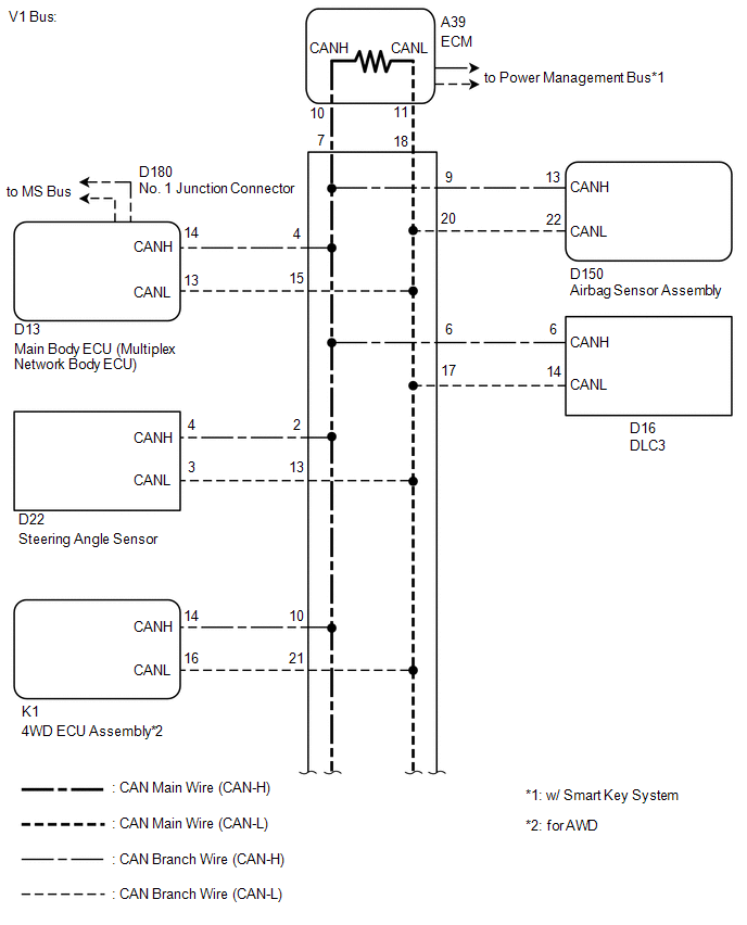
- Short between CAN bus lines
- ECM
- Airbag sensor assembly
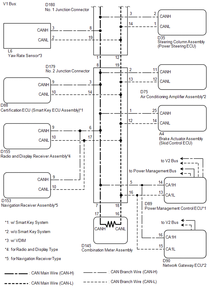
- Power management control ECU*1
- Certification ECU (smart key ECU assembly)*1
- Air conditioning amplifier assembly*2
- Network gateway ECU*2
- Main body ECU (multiplex network body ECU)
- Combination meter assembly
- 4WD ECU assembly*3
- Yaw rate sensor*4
- Brake actuator assembly (skid control ECU)
- Steering angle sensor
- Steering column assembly (power steering ECU)
- Radio and display receiver assembly*5
- Navigation receiver assembly*6
- No. 1 junction connector
- No. 2 junction connector
| Last Modified: 08-28-2024 | 6.11:8.1.0 | Doc ID: RM100000000VJDX |
| Model Year Start: 2016 | Model: Sienna | Prod Date Range: [12/2015 - 08/2016] |
| Title: NETWORKING: CAN COMMUNICATION SYSTEM: Check CAN Bus Lines for Short Circuit; 2016 MY Sienna [12/2015 - 08/2016] | ||
|
Check CAN Bus Lines for Short Circuit |
DESCRIPTION
There may be a short circuit between the CAN bus lines when the resistance between terminals 6 (CANH) and 14 (CANL) of the DLC3 is below 54 Ω.
|
Symptom |
Trouble Area |
|---|---|
|
Resistance between terminals 6 (CANH) and 14 (CANL) of the DLC3 is below 54 Ω. |
|
- *1: w/ Smart Key System
- *2: w/o Smart Key System
- *3: for AWD
- *4: w/ VDIM
- *5: for Radio and Display Type
- *6: for Navigation Receiver Type
WIRING DIAGRAM
CAUTION / NOTICE / HINT
NOTICE:
- Turn the ignition switch off before measuring the resistances between CAN bus main wires and between CAN bus branch wires.
- Turn the ignition switch off before inspecting CAN bus wires for a ground short.
- After the ignition switch is turned off, check that the key reminder warning system and light reminder warning system are not operating.
- Before measuring the resistance, leave the vehicle as is for at least 1 minute and do not operate the ignition switch, any other switches or the doors. If any doors need to be opened in order to check connectors, open the doors and leave them open.
HINT:
- Operating the ignition switch, any other switches or a door triggers related ECU and sensor communication on the CAN. This communication will cause the resistance value to change.
- Even after DTCs are cleared, if a DTC is stored again after driving the vehicle for a while, the malfunction may be occurring due to vibration of the vehicle. In such a case, wiggling the ECUs or wire harness while performing the inspection below may help determine the cause of the malfunction.
PROCEDURE
|
1. |
PRECAUTION |
NOTICE:
After turning the ignition switch off, waiting time may be required before disconnecting the cable from the battery terminal. Therefore, make sure to read the disconnecting the cable from the battery terminal notice before proceeding with work (See page
![2016 MY Sienna [12/2015 - 08/2016]; INTRODUCTION: REPAIR INSTRUCTION: PRECAUTION](/t3Portal/stylegraphics/info.gif) ).
).
|

|
2. |
DISCONNECT CABLE FROM NEGATIVE BATTERY TERMINAL |
(a) Disconnect the cable from the negative (-) battery terminal before measuring the resistances of the main wire and the branch wire.
CAUTION:
Wait at least 90 seconds after disconnecting the cable from the negative (-) battery terminal to disable the SRS system.
NOTICE:
When disconnecting the cable, some systems need to be initialized after the cable is reconnected (See page
).
|
|
3. |
CHECK FOR SHORT IN CAN BUS WIRES (DLC3 BRANCH WIRE) |
|
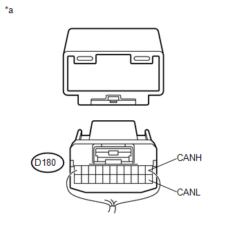
(a) Disconnect the D180 No. 1 junction connector connector. |
|
(b) Measure the resistance according to the value(s) in the table below.
Standard Resistance:
|
Tester Connection |
Switch Condition |
Specified Condition |
|---|---|---|
|
D16-6 (CANH) - D16-14 (CANL) |
Ignition switch off |
200 Ω or higher |
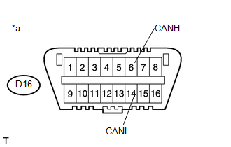
Text in Illustration
|
*a |
Front view of DLC3 |
| NG |

|
REPAIR OR REPLACE CAN BRANCH WIRE CONNECTED TO DLC3 (CAN-H, CAN-L) |
|
|
4. |
CONNECT CONNECTOR |
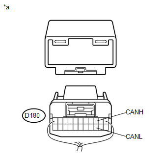
(a) Reconnect the D180 No. 1 junction connector connector.
|
|
5. |
CHECK FOR SHORT IN CAN BUS WIRES (NO. 2 JUNCTION CONNECTOR SIDE) |
|
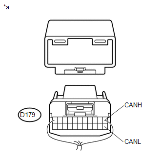
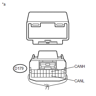
(a) Disconnect the D179 No. 2 junction connector connector. |
|
(b) Measure the resistance according to the value(s) in the table below.
Standard Resistance:
|
Tester Connection |
Switch Condition |
Specified Condition |
|---|---|---|
|
D16-6 (CANH) - D16-14 (CANL) |
Ignition switch off |
108 to 132 Ω |
Text in Illustration
|
*a |
Front view of DLC3 |
| NG |
|
|
|
6. |
CHECK FOR SHORT IN CAN BUS WIRES (NO. 2 JUNCTION CONNECTOR - CERTIFICATION ECU (SMART KEY ECU ASSEMBLY)) |
HINT:
For vehicle without smart key system, go to step 6.
|
(a) Measure the resistance according to the value(s) in the table below. Standard Resistance:
Text in Illustration
|
|

| NG |
|
|
|
7. |
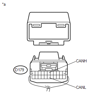
CHECK FOR SHORT IN CAN BUS WIRES (NO. 2 JUNCTION CONNECTOR - AIR CONDITIONING AMPLIFIER ASSEMBLY) |
HINT:
For vehicle with smart key system, go to step 7.
|
(a) Measure the resistance according to the value(s) in the table below. Standard Resistance:
Text in Illustration
|
|
| NG |
|
|
|
8. |
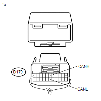
CHECK FOR SHORT IN CAN BUS WIRES (NO. 2 JUNCTION CONNECTOR - BRAKE ACTUATOR ASSEMBLY (SKID CONTROL ECU)) |
|
(a) Measure the resistance according to the value(s) in the table below. Standard Resistance:
Text in Illustration
|
|
| NG |
|
|
|
9. |
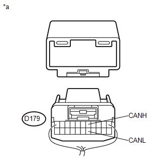
CHECK FOR SHORT IN CAN BUS WIRES (NO. 2 JUNCTION CONNECTOR - RADIO AND DISPLAY RECEIVER ASSEMBLY) |
HINT:
Except radio and display type, go to step 10.
|
(a) Measure the resistance according to the value(s) in the table below. Standard Resistance:
Text in Illustration
|
|
| NG |
|
|
|
10. |
CHECK FOR SHORT IN CAN BUS WIRES (NO. 2 JUNCTION CONNECTOR - NAVIGATION RECEIVER ASSEMBLY) |
HINT:
Except navigation receiver type, go to step 11.
|
(a) Measure the resistance according to the value(s) in the table below. Standard Resistance:
Text in Illustration
|
|
| NG |
|
|
|
11. |
CHECK FOR SHORT IN CAN BUS WIRES (NO. 2 JUNCTION CONNECTOR - POWER MANAGEMENT CONTROL ECU) |
HINT:
For vehicle without smart key system, go to step 12.
|
(a) Measure the resistance according to the value(s) in the table below. Standard Resistance:
Text in Illustration
|
|
| NG |
|
|
|
12. |
CHECK FOR SHORT IN CAN BUS WIRES (NO. 2 JUNCTION CONNECTOR - NETWORK GATEWAY ECU) |
HINT:
For vehicle with smart key system, go to step 13.
|
(a) Measure the resistance according to the value(s) in the table below. Standard Resistance:
Text in Illustration
|
|
| NG |
|
|
|
13. |
CHECK FOR SHORT IN CAN BUS WIRES (NO. 2 JUNCTION CONNECTOR - COMBINATION METER ASSEMBLY) |
|
(a) Measure the resistance according to the value(s) in the table below. Standard Resistance:
Text in Illustration
|
|

| OK |
|
REPAIR OR REPLACE NO. 2 JUNCTION CONNECTOR |
| NG |
|
|
14. |
CONNECT CONNECTOR |
(a) Reconnect the D179 No. 2 junction connector connector.
|
|
15. |
CHECK FOR SHORT IN CAN BUS WIRES (NO. 1 JUNCTION CONNECTOR - NO. 2 JUNCTION CONNECTOR) |
|
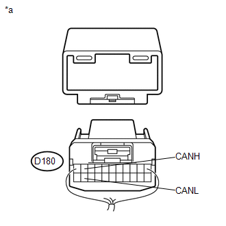
(a) Disconnect the No. 1 junction connector connector. |
|
(b) Measure the resistance according to the value(s) in the table below.
Standard Resistance:
|
Tester Connection |
Switch Condition |
Specified Condition |
|---|---|---|
|
D180-1 (CANH) - D180-12 (CANL) |
Ignition switch off |
108 to 132 Ω |
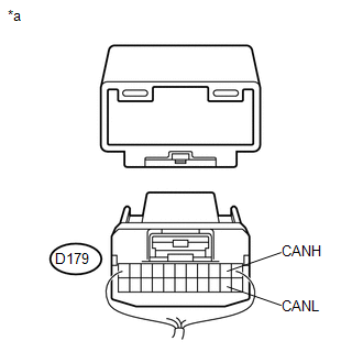
Text in Illustration
|
*a |
Rear view of wire harness connector (to No. 1 Junction Connector) |
| NG |
|
REPAIR OR REPLACE CAN MAIN WIRE OR CONNECTOR (NO. 1 JUNCTION CONNECTOR - NO. 2 JUNCTION CONNECTOR) |
|
|
16. |
CHECK FOR SHORT IN CAN BUS WIRES (NO. 1 JUNCTION CONNECTOR - STEERING ANGLE SENSOR) |
|
(a) Measure the resistance according to the value(s) in the table below. Standard Resistance:
Text in Illustration
|
|

| NG |
|
|
|
17. |
CHECK FOR SHORT IN CAN BUS WIRES (NO. 1 JUNCTION CONNECTOR - STEERING COLUMN ASSEMBLY (POWER STEERING ECU)) |
|
(a) Measure the resistance according to the value(s) in the table below. Standard Resistance:
Text in Illustration
|
|
| NG |
|
|
|
18. |
CHECK FOR SHORT IN CAN BUS WIRES (NO. 1 JUNCTION CONNECTOR - MAIN BODY ECU (MULTIPLEX NETWORK BODY ECU)) |
|
(a) Measure the resistance according to the value(s) in the table below. Standard Resistance:
Text in Illustration
|
|

| NG |
|
|
|
19. |
CHECK FOR SHORT IN CAN BUS WIRES (NO. 1 JUNCTION CONNECTOR - YAW RATE SENSOR) |
HINT:
For vehicle without VDIM, go to step 20.
|
(a) Measure the resistance according to the value(s) in the table below. Standard Resistance:
Text in Illustration
|
|

| NG |
|
|
|
20. |
CHECK FOR SHORT IN CAN BUS WIRES (NO. 1 JUNCTION CONNECTOR - AIRBAG SENSOR ASSEMBLY) |
|
(a) Measure the resistance according to the value(s) in the table below. Standard Resistance:
Text in Illustration
|
|

| NG |
|
|
|
21. |
CHECK FOR SHORT IN CAN BUS WIRES (NO. 1 JUNCTION CONNECTOR - 4WD ECU ASSEMBLY) |
HINT:
Except AWD, go to step 22.
|
(a) Measure the resistance according to the value(s) in the table below. Standard Resistance:
Text in Illustration
|
|
| NG |
|
|
|
22. |
CHECK FOR SHORT IN CAN BUS WIRES (NO. 1 JUNCTION CONNECTOR - ECM) |
|
(a) Measure the resistance according to the value(s) in the table below. Standard Resistance:
Text in Illustration
|
|

| OK |
|
REPAIR OR REPLACE NO. 1 JUNCTION CONNECTOR |
| NG |
|
|
23. |
CONNECT CONNECTOR |
(a) Reconnect the D179 No. 2 junction connector connector.
|
|
24. |
CHECK FOR SHORT IN CAN BUS WIRES (CERTIFICATION ECU (SMART KEY ECU ASSEMBLY)) |
|
(a) Disconnect the certification ECU (smart key ECU assembly) connector. |
|
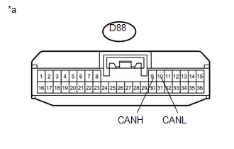
(b) Measure the resistance according to the value(s) in the table below.
Standard Resistance:
|
Tester Connection |
Switch Condition |
Specified Condition |
|---|---|---|
|
D88-9 (CANH) - D88-10 (CANL) |
Ignition switch off |
54 to 69 Ω |
Text in Illustration
|
*a |
Front view of wire harness connector (to Certification ECU (Smart Key ECU Assembly)) |
| OK |
|
| NG |
|
REPAIR OR REPLACE CAN BRANCH WIRE CONNECTED TO CERTIFICATION ECU (SMART KEY ECU ASSEMBLY) (CAN-H, CAN-L) |
|
25. |
CONNECT CONNECTOR |
(a) Reconnect the D179 No. 2 junction connector connector.
|
|
26. |
CHECK FOR SHORT IN CAN BUS WIRES (AIR CONDITIONING AMPLIFIER ASSEMBLY) |
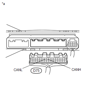
(a) Disconnect the air conditioning amplifier assembly connector.
(b) Measure the resistance according to the value(s) in the table below.
Standard Resistance:
|
Tester Connection |
Switch Condition |
Specified Condition |
|---|---|---|
|
D75-11 (CANH) - D75-12 (CANL) |
Ignition switch off |
54 to 69 Ω |
Text in Illustration
|
*a |
Rear view of wire harness connector (to Air Conditioning Amplifier Assembly) |
| OK |
|
| NG |
|
REPAIR OR REPLACE CAN BRANCH WIRE CONNECTED TO AIR CONDITIONING AMPLIFIER ASSEMBLY (CAN-H, CAN-L) |
|
27. |
CONNECT CONNECTOR |
(a) Reconnect the D179 No. 2 junction connector connector.
|
|
28. |
CHECK FOR SHORT IN CAN BUS WIRES (BRAKE ACTUATOR ASSEMBLY (SKID CONTROL ECU)) |
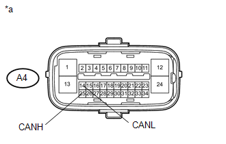
(a) Disconnect the brake actuator assembly (skid control ECU) connector.
(b) Measure the resistance according to the value(s) in the table below.
Standard Resistance:
|
Tester Connection |
Switch Condition |
Specified Condition |
|---|---|---|
|
A4-25 (CANH) - A4-14 (CANL) |
Ignition switch off |
54 to 69 Ω |
Text in Illustration
|
*a |
Front view of wire harness connector (to Brake Actuator Assembly (Skid Control ECU)) |
| OK |
|
| NG |
|
REPAIR OR REPLACE CAN BRANCH WIRE CONNECTED TO BRAKE ACTUATOR ASSEMBLY (SKID CONTROL ECU) (CAN-H, CAN-L) |
|
29. |
CONNECT CONNECTOR |
(a) Reconnect the D179 No. 2 junction connector connector.
|
|
30. |
CHECK FOR SHORT IN CAN BUS WIRES (RADIO AND DISPLAY RECEIVER ASSEMBLY) |
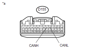
(a) Disconnect the radio and display receiver assembly connector.
(b) Measure the resistance according to the value(s) in the table below.
Standard Resistance:
|
Tester Connection |
Switch Condition |
Specified Condition |
|---|---|---|
|
D155-9 (CANH) - D155-10 (CANL) |
Ignition switch off |
54 to 69 Ω |
Text in Illustration
|
*a |
Front view of wire harness connector (to Radio and Display Receiver Assembly) |
| OK |
|
| NG |
|
REPAIR OR REPLACE CAN BRANCH WIRE CONNECTED TO RADIO AND DISPLAY RECEIVER ASSEMBLY (CAN-H, CAN-L) |
|
31. |
CONNECT CONNECTOR |
(a) Reconnect the D179 No. 2 junction connector connector.
|
|
32. |
CHECK FOR SHORT IN CAN BUS WIRES (NAVIGATION RECEIVER ASSEMBLY) |
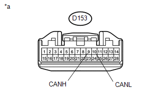
(a) Disconnect the navigation receiver assembly connector.
(b) Measure the resistance according to the value(s) in the table below.
Standard Resistance:
|
Tester Connection |
Switch Condition |
Specified Condition |
|---|---|---|
|
D153-9 (CANH) - D153-10 (CANL) |
Ignition switch off |
54 to 69 Ω |
Text in Illustration
|
*a |
Front view of wire harness connector (to Navigation Receiver Assembly) |
| OK |
|
| NG |
|
REPAIR OR REPLACE CAN BRANCH WIRE CONNECTED TO NAVIGATION RECEIVER ASSEMBLY (CAN-H, CAN-L) |
|
33. |
CONNECT CONNECTOR |
(a) Reconnect the D179 No. 2 junction connector connector.
|
|
34. |
CHECK FOR SHORT IN CAN BUS WIRES (POWER MANAGEMENT CONTROL ECU) |
|
(a) Disconnect the power management control ECU connector. |
|
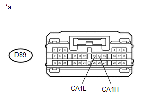
(b) Measure the resistance according to the value(s) in the table below.
Standard Resistance:
|
Tester Connection |
Switch Condition |
Specified Condition |
|---|---|---|
|
D89-14 (CA1H) - D89-13 (CA1L) |
Ignition switch off |
54 to 69 Ω |
Text in Illustration
|
*a |
Front view of wire harness connector (to Power Management Control ECU) |
| OK |
|
| NG |
|
REPAIR OR REPLACE CAN BRANCH WIRE CONNECTED TO POWER MANAGEMENT CONTROL ECU (CAN-H, CAN-L) |
|
35. |
CONNECT CONNECTOR |
(a) Reconnect the D179 No. 2 junction connector connector.
|
|
36. |
CHECK FOR SHORT IN CAN BUS WIRES (NETWORK GATEWAY ECU) |
|
(a) Disconnect the network gateway ECU connector. |
|
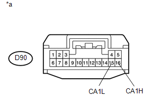
(b) Measure the resistance according to the value(s) in the table below.
Standard Resistance:
|
Tester Connection |
Switch Condition |
Specified Condition |
|---|---|---|
|
D90-16 (CA1H) - D90-15 (CA1L) |
Ignition switch off |
54 to 69 Ω |
Text in Illustration
|
*a |
Front view of wire harness connector (to Network Gateway ECU) |
| OK |
|
| NG |
|
REPAIR OR REPLACE CAN BRANCH WIRE CONNECTED TO NETWORK GATEWAY ECU (CAN-H, CAN-L) |
|
37. |
CONNECT CONNECTOR |
(a) Reconnect the D179 No. 2 junction connector connector.
|
|
38. |
CHECK FOR SHORT IN CAN BUS WIRES (COMBINATION METER ASSEMBLY) |
|
(a) Disconnect the combination meter assembly connector. |
|
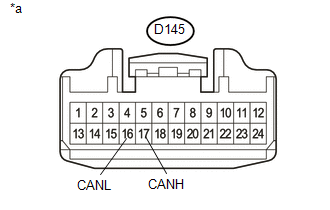
(b) Measure the resistance according to the value(s) in the table below.
Standard Resistance:
|
Tester Connection |
Switch Condition |
Specified Condition |
|---|---|---|
|
D145-17 (CANH) - D145-16 (CANL) |
Ignition switch off |
108 to 132 Ω |
Text in Illustration
|
*a |
Front view of wire harness connector (to Combination Meter Assembly) |
| OK |
|
| NG |
|
REPAIR OR REPLACE CAN MAIN WIRE CONNECTED TO COMBINATION METER ASSEMBLY (CAN-H, CAN-L) |
|
39. |
CONNECT CONNECTOR |
(a) Reconnect the D180 No. 1 junction connector connector.
|
|
40. |
CHECK FOR SHORT IN CAN BUS WIRES (STEERING ANGLE SENSOR) |
|
(a) Disconnect the steering angle sensor connector. |
|
(b) Measure the resistance according to the value(s) in the table below.
Standard Resistance:
|
Tester Connection |
Switch Condition |
Specified Condition |
|---|---|---|
|
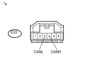
D22-4 (CANH) - D22-3 (CANL) |
Ignition switch off |
54 to 69 Ω |
Text in Illustration
|
*a |
Front view of wire harness connector (to Steering Angle Sensor) |
| OK |
|
| NG |
|
REPAIR OR REPLACE CAN BRANCH WIRE CONNECTED TO STEERING ANGLE SENSOR (CAN-H, CAN-L) |
|
41. |
CONNECT CONNECTOR |
(a) Reconnect the D180 No. 1 junction connector connector.
|
|
42. |
CHECK FOR SHORT IN CAN BUS WIRES (STEERING COLUMN ASSEMBLY (POWER STEERING ECU)) |
|
(a) Disconnect the steering column assembly (power steering ECU) connector. |
|
(b) Measure the resistance according to the value(s) in the table below.
Standard Resistance:
|
Tester Connection |
Switch Condition |
Specified Condition |
|---|---|---|
|
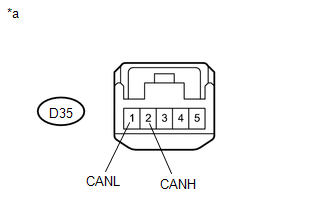
D35-2 (CANH) - D35-1 (CANL) |
Ignition switch off |
54 to 69 Ω |
Text in Illustration
|
*a |
Front view of wire harness connector (to Steering Column Assembly (Power Steering ECU)) |
| OK |
|
| NG |
|
REPAIR OR REPLACE CAN BRANCH WIRE CONNECTED TO STEERING COLUMN ASSEMBLY (POWER STEERING ECU) (CAN-H, CAN-L) |
|
43. |
CONNECT CONNECTOR |
(a) Reconnect the D180 No. 1 junction connector connector.
|
|
44. |
CHECK FOR SHORT IN CAN BUS WIRES (MAIN BODY ECU (MULTIPLEX NETWORK BODY ECU)) |
|
(a) Disconnect the main body ECU (multiplex network body ECU) connector. |
|
(b) Measure the resistance according to the value(s) in the table below.
Standard Resistance:
|
Tester Connection |
Switch Condition |
Specified Condition |
|---|---|---|
|
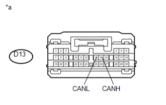
D13-14 (CANH) - D13-13 (CANL) |
Ignition switch off |
54 to 69 Ω |
Text in Illustration
|
*a |
Front view of wire harness connector (to Main Body ECU (Multiplex Network Body ECU)) |
| OK |
|
| NG |
|
REPAIR OR REPLACE CAN BRANCH WIRE CONNECTED TO MAIN BODY ECU (MULTIPLEX NETWORK BODY ECU) (CAN-H, CAN-L) |
|
45. |
CONNECT CONNECTOR |
(a) Reconnect the D180 No. 1 junction connector connector.
|
|
46. |
CHECK FOR SHORT IN CAN BUS WIRES (YAW RATE SENSOR) |
|
(a) Disconnect the yaw rate sensor connector. |
|
(b) Measure the resistance according to the value(s) in the table below.
Standard Resistance:
|
Tester Connection |
Switch Condition |
Specified Condition |
|---|---|---|
|
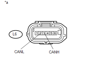
L6-3 (CANH) - L6-2 (CANL) |
Ignition switch off |
54 to 69 Ω |
Text in Illustration
|
*a |
Front view of wire harness connector (to Yaw Rate Sensor) |
| OK |
|
| NG |
|
REPAIR OR REPLACE CAN BRANCH WIRE CONNECTED TO YAW RATE SENSOR (CAN-H, CAN-L) |
|
47. |
CONNECT CONNECTOR |
(a) Reconnect the D180 No. 1 junction connector connector.
|
|
48. |
CHECK SHORT IN CAN BUS WIRES (AIRBAG SENSOR ASSEMBLY) |
|
(a) Disconnect the airbag sensor assembly connector. |
|
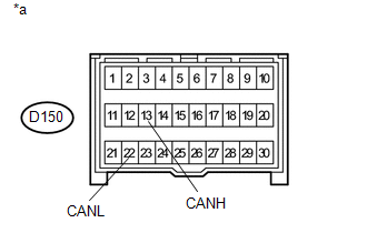
(b) Measure the resistance according to the value(s) in the table below.
Standard Resistance:
|
Tester Connection |
Switch Condition |
Specified Condition |
|---|---|---|
|
D150-13 (CANH) - D150-22 (CANL) |
Ignition switch off |
54 to 69 Ω |
Text in Illustration
|
*a |
Front view of wire harness connector (to Airbag Sensor Assembly) |
| OK |
|
| NG |
|
REPAIR OR REPLACE CAN BRANCH WIRE CONNECTED TO AIRBAG SENSOR ASSEMBLY (CAN-H, CAN-L) |
|
49. |
CONNECT CONNECTOR |
(a) Reconnect the D180 No. 1 junction connector connector.
|
|
50. |
CHECK SHORT IN CAN BUS WIRES (4WD ECU ASSEMBLY) |
|
(a) Disconnect the 4WD ECU assembly connector. |
|
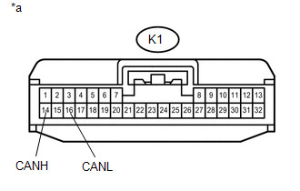
(b) Measure the resistance according to the value(s) in the table below.
Standard Resistance:
|
Tester Connection |
Switch Condition |
Specified Condition |
|---|---|---|
|
K1-14 (CANH) - K1-16 (CANL) |
Ignition switch off |
54 to 69 Ω |
Text in Illustration
|
*a |
Front view of wire harness connector (to 4WD ECU Assembly) |
| OK |
|
| NG |
|
REPAIR OR REPLACE CAN BRANCH WIRE CONNECTED TO 4WD ECU ASSEMBLY (CAN-H, CAN-L) |
|
51. |
CONNECT CONNECTOR |
(a) Reconnect the D180 No. 1 junction connector connector.
|
|
52. |
CHECK FOR SHORT IN CAN BUS WIRES (ECM) |
|
(a) Disconnect the ECM connector. |
|
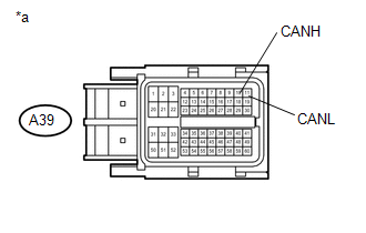
(b) Measure the resistance according to the value(s) in the table below.
Standard Resistance:
|
Tester Connection |
Switch Condition |
Specified Condition |
|---|---|---|
|
A39-10 (CANH) - A39-11 (CANL) |
Ignition switch off |
108 to 132 Ω |
Text in Illustration
|
*a |
Front view of wire harness connector (to ECM) |
| OK |
|
| NG |
|
REPAIR OR REPLACE CAN MAIN WIRE CONNECTED TO ECM (CAN-H, CAN-L) |
|
|
|