- One side of CAN branch wire is open
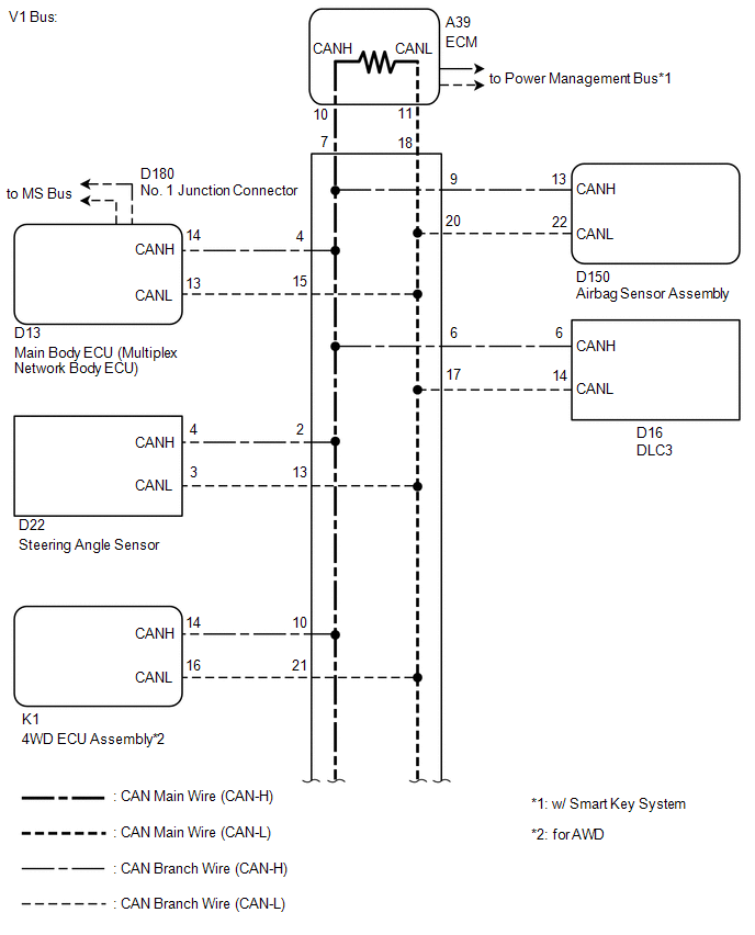
- Airbag sensor assembly
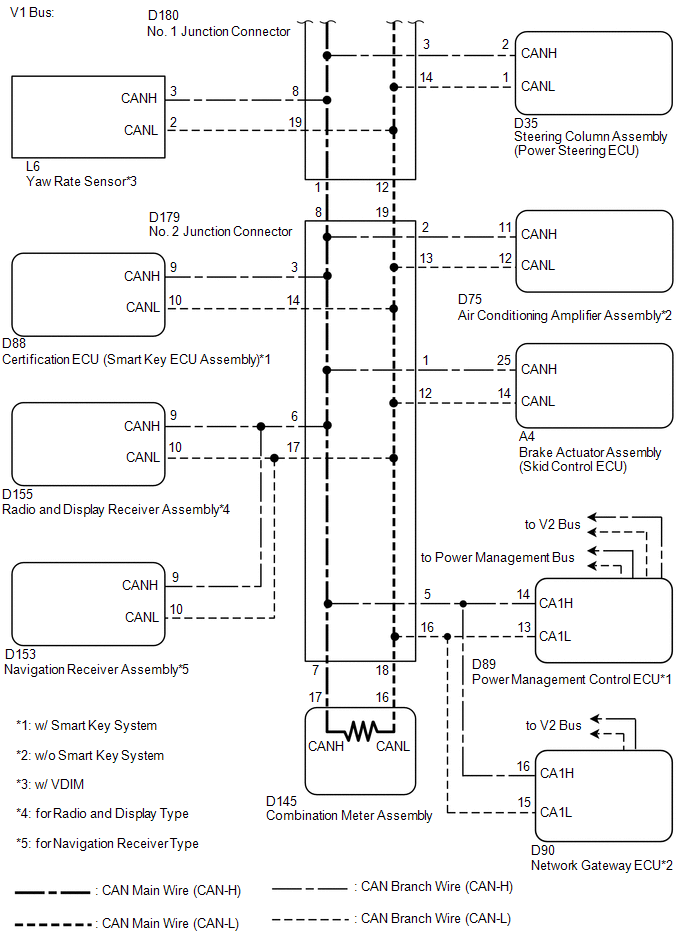
- Power management control ECU*1
- Certification ECU (smart key ECU assembly)*1
- Air conditioning amplifier assembly*2
- Network gateway ECU*2
- Main body ECU (multiplex network body ECU)
- 4WD ECU assembly*3
- Yaw rate sensor*4
- Brake actuator assembly (skid control ECU)
- Steering angle sensor
- Steering column assembly (power steering ECU)
- Radio and display receiver assembly*5
- Navigation receiver assembly*6
| Last Modified: 08-28-2024 | 6.11:8.1.0 | Doc ID: RM100000000VJDW |
| Model Year Start: 2016 | Model: Sienna | Prod Date Range: [12/2015 - 08/2016] |
| Title: NETWORKING: CAN COMMUNICATION SYSTEM: Open in One Side of CAN Branch Line; 2016 MY Sienna [12/2015 - 08/2016] | ||
|
Open in One Side of CAN Branch Line |
DESCRIPTION
If 2 or more ECUs and/or sensors do not appear on the Techstream "CAN Bus Check" screen, one side of the CAN branch wire may be open (One side of the CANH [branch wire]/CANL [branch wire] of the ECU and/or sensor is open).
|
Symptom |
Trouble Area |
|---|---|
|
2 or more ECUs and/or sensors do not appear on the Techstream "CAN Bus Check" screen. |
|
- *1: w/ Smart Key System
- *2: w/o Smart Key System
- *3: for AWD
- *4: w/ VDIM
- *5: for Radio and Display Type
- *6: for Navigation Receiver Type
WIRING DIAGRAM
CAUTION / NOTICE / HINT
CAUTION:
Wait at least 90 seconds after disconnecting the cable from the negative (-) battery terminal to prevent airbag and seat belt pretensioner activation.
NOTICE:
- Turn the ignition switch off before measuring the resistances between CAN bus main wires and between CAN bus branch wires.
- Turn the ignition switch off before inspecting CAN bus wires for a ground short.
- After the ignition switch is turned off, check that the key reminder warning system and light reminder warning system are not operating.
- Before measuring the resistance, first disconnect the cable from the negative battery terminal and confirm that the alarm function is no longer operating. Then, leave the vehicle as is for at least 1 minute and do not operate the ignition switch, any other switches or the doors. If any doors need to be opened in order to check connectors, open the doors and leave them open.
-
When disconnecting the cable, some systems need to be initialized after the cable is reconnected (See page
![2016 MY Sienna [12/2015 - 08/2016]; INTRODUCTION: REPAIR INSTRUCTION: INITIALIZATION](/t3Portal/stylegraphics/info.gif) ).
).
HINT:
- Perform the following inspection for the ECUs (sensors) which are not displayed on the Techstream. If a malfunction cannot be identified, perform the following inspections for the ECUs (sensors) connected to the CAN communication system.
- Do not remove the airbag sensor assembly and ECM, as they are the end parts of the circuit. If removed, CAN communication will not be possible.
- The open circuit confirmation of the airbag sensor assembly, ECM and main wire is performed in the Check CAN Bus Line procedure of How to Proceed with Troubleshooting. This inspection only has procedures for checking for an open circuit on one side of the CAN branch wire.
PROCEDURE
|
1. |
CHECK FOR OPEN IN ONE SIDE OF BRANCH WIRE (4WD ECU ASSEMBLY) |
HINT:
Except AWD, go to step 3.
(a) Disconnect the K1 4WD ECU assembly connector.
(b) Select "CAN Bus Check" on the Techstream (See page
).
Result
|
Result |
Proceed to |
|---|---|
|
"Four Wheel Drive Control" not displayed on the Techstream. |
A |
|
Several ECUs and sensors other than "Four Wheel Drive Control" not displayed on the Techstream. |
B |
| B |

|
|

|
2. |
CHECK FOR OPEN IN ONE SIDE OF BRANCH WIRE (4WD ECU ASSEMBLY BRANCH WIRE) |
|
(a) Measure the resistance according to the value(s) in the table below. Standard Resistance:
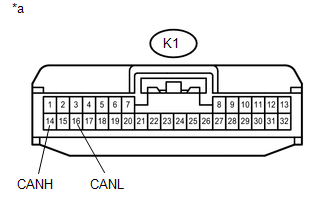
Text in Illustration
|
|
| OK |
|
| NG |
|
REPAIR OR REPLACE CAN BRANCH WIRE OR CONNECTOR (4WD ECU ASSEMBLY) |
|
3. |
CHECK FOR OPEN IN ONE SIDE OF BRANCH WIRE (YAW RATE SENSOR) |
HINT:
For vehicle without VDIM, go to step 5.
(a) Disconnect the L6 yaw rate sensor connector.
(b) Select "CAN Bus Check" on the Techstream (See page
).
Result
|
Result |
Proceed to |
|---|---|
|
"Yaw Rate Sensor" not displayed on the Techstream. |
A |
|
Several ECUs and sensors other than "Yaw Rate Sensor" not displayed on the Techstream. |
B |
| B |
|
|
|
4. |
CHECK FOR OPEN IN ONE SIDE OF BRANCH WIRE (YAW RATE SENSOR BRANCH WIRE) |
|
(a) Measure the resistance according to the value(s) in the table below. Standard Resistance:
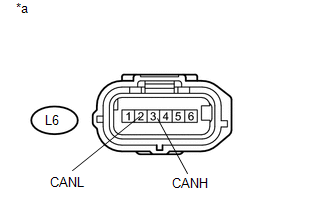
Text in Illustration
|
|
| OK |
|
| NG |
|
REPAIR OR REPLACE CAN BRANCH WIRE OR CONNECTOR (YAW RATE SENSOR) |
|
5. |
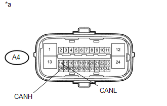
CHECK FOR OPEN IN ONE SIDE OF BRANCH WIRE (BRAKE ACTUATOR ASSEMBLY (SKID CONTROL ECU)) |
(a) Disconnect the A4 brake actuator assembly (skid control ECU) connector.
(b) Select "CAN Bus Check" on the Techstream (See page
).
Result
|
Result |
Proceed to |
|---|---|
|
"Skid Control (ABS/VSC/TRAC)" not displayed on the Techstream. |
A |
|
Several ECUs and sensors other than "Skid Control (ABS/VSC/TRAC)" not displayed on the Techstream. |
B |
| B |
|
|
|
6. |
CHECK FOR OPEN IN ONE SIDE OF BRANCH WIRE (BRAKE ACTUATOR ASSEMBLY (SKID CONTROL ECU) BRANCH WIRE) |
|
(a) Measure the resistance according to the value(s) in the table below. Standard Resistance:
Text in Illustration
|
|
| OK |
|
| NG |
|
REPAIR OR REPLACE CAN BRANCH WIRE OR CONNECTOR (BRAKE ACTUATOR ASSEMBLY (SKID CONTROL ECU)) |
|
7. |
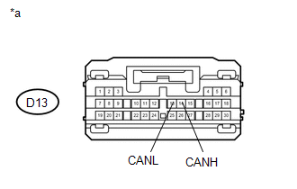
CHECK FOR OPEN IN ONE SIDE OF BRANCH WIRE (MAIN BODY ECU (MULTIPLEX NETWORK BODY ECU)) |
(a) Disconnect the D13 main body ECU (multiplex network body ECU) connector.
(b) Select "CAN Bus Check" on the Techstream (See page
).
Result
|
Result |
Proceed to |
|---|---|
|
"Main Body" not displayed on the Techstream. |
A |
|
Several ECUs and sensors other than "Main Body" not displayed on the Techstream. |
B |
| B |
|
|
|
8. |
CHECK FOR OPEN IN ONE SIDE OF BRANCH WIRE (MAIN BODY ECU (MULTIPLEX NETWORK BODY ECU) BRANCH WIRE) |
|
(a) Measure the resistance according to the value(s) in the table below. Standard Resistance:
Text in Illustration
|
|
| OK |
|
| NG |
|
REPAIR OR REPLACE CAN BRANCH WIRE OR CONNECTOR (MAIN BODY ECU (MULTIPLEX NETWORK BODY ECU)) |
|
9. |
CHECK FOR OPEN IN ONE SIDE OF BRANCH WIRE (AIRBAG SENSOR ASSEMBLY) |
(a) Disconnect the D150 airbag sensor assembly connector.
(b) Select "CAN Bus Check" on the Techstream (See page
).
Result
|
Result |
Proceed to |
|---|---|
|
"SRS Airbag" not displayed on the Techstream. |
A |
|
Several ECUs and sensors other than "SRS Airbag" not displayed on the Techstream. |
B |
| B |
|
|
|
10. |
CHECK FOR OPEN IN ONE SIDE OF BRANCH WIRE (AIRBAG SENSOR ASSEMBLY BRANCH WIRE) |
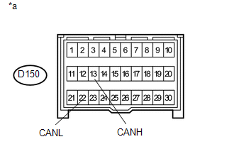
(a) Measure the resistance according to the value(s) in the table below.
Standard Resistance:
|
Tester Connection |
Switch Condition |
Specified Condition |
|---|---|---|
|
D150-13 (CANH) - D150-22 (CANL) |
Ignition switch off |
54 to 69 Ω |
Text in Illustration
|
*a |
Front view of wire harness connector (to Airbag Sensor Assembly) |
| OK |
|
| NG |
|
REPAIR OR REPLACE CAN BRANCH WIRE OR CONNECTOR (AIRBAG SENSOR ASSEMBLY) |
|
11. |
CHECK FOR OPEN IN ONE SIDE OF BRANCH WIRE (STEERING ANGLE SENSOR) |
(a) Disconnect the D22 steering angle sensor connector.
(b) Select "CAN Bus Check" on the Techstream (See page
).
Result
|
Result |
Proceed to |
|---|---|
|
"Spiral Cable (Steering Angle Sensor)" not displayed on the Techstream. |
A |
|
Several ECUs and sensors other than "Spiral Cable (Steering Angle Sensor)" not displayed on the Techstream. |
B |
| B |
|
|
|
12. |
CHECK FOR OPEN IN ONE SIDE OF BRANCH WIRE (STEERING ANGLE SENSOR BRANCH WIRE) |
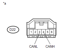
(a) Measure the resistance according to the value(s) in the table below.
Standard Resistance:
|
Tester Connection |
Switch Condition |
Specified Condition |
|---|---|---|
|
D22-4 (CANH) - D22-3 (CANL) |
Ignition switch off |
54 to 69 Ω |
Text in Illustration
|
*a |
Front view of wire harness connector (to Steering Angle Sensor) |
| OK |
|
| NG |
|
REPAIR OR REPLACE CAN BRANCH WIRE OR CONNECTOR (STEERING ANGLE SENSOR) |
|
13. |
CHECK FOR OPEN IN ONE SIDE OF BRANCH WIRE (CERTIFICATION ECU (SMART KEY ECU ASSEMBLY)) |
HINT:
For vehicle without smart key system, go to step 15.
(a) Disconnect the D88 certification ECU (smart key ECU assembly) connector.
(b) Select "CAN Bus Check" on the Techstream (See page
).
Result
|
Result |
Proceed to |
|---|---|
|
"Certification (Smart)" not displayed on the Techstream. |
A |
|
Several ECUs and sensors other than "Certification (Smart)" not displayed on the Techstream. |
B |
| B |
|
|
|
14. |
CHECK FOR OPEN IN ONE SIDE OF BRANCH WIRE (CERTIFICATION ECU (SMART KEY ECU ASSEMBLY) BRANCH WIRE) |
(a) Measure the resistance according to the value(s) in the table below.
Standard Resistance:
|
Tester Connection |
Switch Condition |
Specified Condition |
|---|---|---|
|
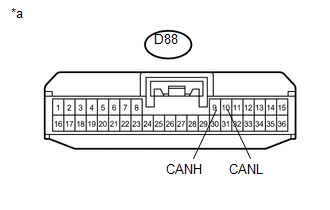
D88-9 (CANH) - D88-10 (CANL) |
Ignition switch off |
54 to 69 Ω |
Text in Illustration
|
*a |
Front view of wire harness connector (to Certification ECU (Smart Key ECU Assembly)) |
| OK |
|
| NG |
|
REPAIR OR REPLACE CAN BRANCH WIRE OR CONNECTOR (CERTIFICATION ECU (SMART KEY ECU ASSEMBLY)) |
|
15. |
CHECK FOR OPEN IN ONE SIDE OF BRANCH WIRE (POWER MANAGEMENT CONTROL ECU) |
HINT:
For vehicle without smart key system, go to step 17.
(a) Disconnect the D89 power management control ECU connector.
(b) Select "CAN Bus Check" on the Techstream (See page
).
Result
|
Result |
Proceed to |
|---|---|
|
"Power Management" not displayed on the Techstream. |
A |
|
Several ECUs and sensors other than "Power Management" not displayed on the Techstream. |
B |
| B |
|
|
|
16. |
CHECK FOR OPEN IN ONE SIDE OF BRANCH WIRE (POWER MANAGEMENT CONTROL ECU BRANCH WIRE) |
(a) Measure the resistance according to the value(s) in the table below.
Standard Resistance:
|
Tester Connection |
Switch Condition |
Specified Condition |
|---|---|---|
|
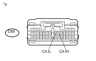
D89-14 (CA1H) - D89-13 (CA1L) |
Ignition switch off |
54 to 69 Ω |
Text in Illustration
|
*a |
Front view of wire harness connector (to Power Management Control ECU) |
| OK |
|
| NG |
|
REPAIR OR REPLACE CAN BRANCH WIRE OR CONNECTOR (POWER MANAGEMENT CONTROL ECU) |
|
17. |
CHECK FOR OPEN IN ONE SIDE OF BRANCH WIRE (AIR CONDITIONING AMPLIFIER ASSEMBLY) |
HINT:
For vehicle with smart key system, go to step 19.
(a) Disconnect the D75 air conditioning amplifier assembly connector.
(b) Select "CAN Bus Check" on the Techstream (See page
).
Result
|
Result |
Proceed to |
|---|---|
|
"Air Conditioning Amplifier" not displayed on the Techstream. |
A |
|
Several ECUs and sensors other than "Air Conditioning Amplifier" not displayed on the Techstream. |
B |
| B |
|
|
|
18. |
CHECK FOR OPEN IN ONE SIDE OF BRANCH WIRE (AIR CONDITIONING AMPLIFIER ASSEMBLY BRANCH WIRE) |
(a) Measure the resistance according to the value(s) in the table below.
Standard Resistance:
|
Tester Connection |
Switch Condition |
Specified Condition |
|---|---|---|
|
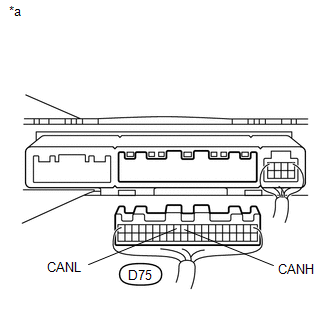
D75-11 (CANH) - D75-12 (CANL) |
Ignition switch off |
54 to 69 Ω |
Text in Illustration
|
*a |
Rear view of wire harness connector (to Air Conditioning Amplifier Assembly) |
| OK |
|
| NG |
|
REPAIR OR REPLACE CAN BRANCH WIRE OR CONNECTOR (AIR CONDITIONING AMPLIFIER ASSEMBLY) |
|
19. |
CHECK FOR OPEN IN ONE SIDE OF BRANCH WIRE (NETWORK GATEWAY ECU) |
HINT:
For vehicle with smart key system, go to step 21.
(a) Disconnect the D90 network gateway ECU connector.
(b) Select "CAN Bus Check" on the Techstream (See page
).
Result
|
Result |
Proceed to |
|---|---|
|
"CAN Gateway" not displayed on the Techstream. |
A |
|
Several ECUs and sensors other than "CAN Gateway" not displayed on the Techstream. |
B |
| B |
|
|
|
20. |
CHECK FOR OPEN IN ONE SIDE OF BRANCH WIRE (NETWORK GATEWAY ECU BRANCH WIRE) |
(a) Measure the resistance according to the value(s) in the table below.
Standard Resistance:
|
Tester Connection |
Switch Condition |
Specified Condition |
|---|---|---|
|
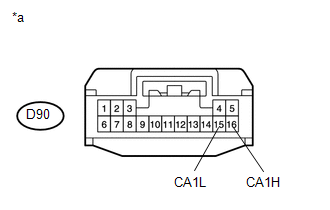
D90-16 (CA1H) - D90-15 (CA1L) |
Ignition switch off |
54 to 69 Ω |
Text in Illustration
|
*a |
Front view of wire harness connector (to Network Gateway ECU) |
| OK |
|
| NG |
|
REPAIR OR REPLACE CAN BRANCH WIRE OR CONNECTOR (NETWORK GATEWAY ECU) |
|
21. |
CHECK FOR OPEN IN ONE SIDE OF BRANCH WIRE (RADIO AND DISPLAY RECEIVER ASSEMBLY) |
HINT:
Except radio and display receiver type, go to step 23.
(a) Disconnect the D155 radio and display receiver assembly connector.
(b) Select "CAN Bus Check" on the Techstream (See page
).
Result
|
Result |
Proceed to |
|---|---|
|
"Display and Navigation (AVN1)" not displayed on the Techstream. |
A |
|
Several ECUs and sensors other than "Display and Navigation (AVN1)" not displayed on the Techstream. |
B |
| B |
|
|
|
22. |
CHECK FOR OPEN IN ONE SIDE OF BRANCH WIRE (RADIO AND DISPLAY RECEIVER ASSEMBLY BRANCH WIRE) |
(a) Measure the resistance according to the value(s) in the table below.
Standard Resistance:
|
Tester Connection |
Switch Condition |
Specified Condition |
|---|---|---|
|
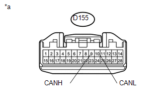
D155-9 (CANH) - D155-10 (CANL) |
Ignition switch off |
54 to 69 Ω |
Text in Illustration
|
*a |
Front view of wire harness connector (to Radio and Display Receiver Assembly) |
| OK |
|
| NG |
|
REPAIR OR REPLACE CAN BRANCH WIRE OR CONNECTOR (RADIO AND DISPLAY RECEIVER ASSEMBLY) |
|
23. |
CHECK FOR OPEN IN ONE SIDE OF BRANCH WIRE (NAVIGATION RECEIVER ASSEMBLY) |
HINT:
Except navigation receiver type, go to step 25.
(a) Disconnect the D153 navigation receiver assembly connector.
(b) Select "CAN Bus Check" on the Techstream (See page
).
Result
|
Result |
Proceed to |
|---|---|
|
"Display and Navigation (AVN1)" not displayed on the Techstream. |
A |
|
Several ECUs and sensors other than "Display and Navigation (AVN1)" not displayed on the Techstream. |
B |
| B |
|
|
|
24. |
CHECK FOR OPEN IN ONE SIDE OF BRANCH WIRE (NAVIGATION RECEIVER ASSEMBLY) |

(a) Measure the resistance according to the value(s) in the table below.
Standard Resistance:
|
Tester Connection |
Switch Condition |
Specified Condition |
|---|---|---|
|
D153-9 (CANH) - D153-10 (CANL) |
Ignition switch off |
54 to 69 Ω |
Text in Illustration
|
*a |
Front view of wire harness connector (to Navigation Receiver Assembly) |
| OK |
|
| NG |
|
REPAIR OR REPLACE CAN BRANCH WIRE OR CONNECTOR (NAVIGATION RECEIVER ASSEMBLY) |
|
25. |
CHECK FOR OPEN IN ONE SIDE OF BRANCH WIRE (STEERING COLUMN ASSEMBLY (POWER STEERING ECU)) |
(a) Measure the resistance according to the value(s) in the table below.
Standard Resistance:
|
Tester Connection |
Switch Condition |
Specified Condition |
|---|---|---|
|
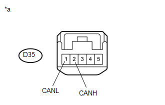
D35-2 (CANH) - D35-1 (CANL) |
Ignition switch off |
54 to 69 Ω |
Text in Illustration
|
*a |
Front view of wire harness connector (to Steering Column Assembly (Power Steering ECU)) |
| OK |
|
| NG |
|
REPAIR OR REPLACE CAN BRANCH WIRE OR CONNECTOR (STEERING COLUMN ASSEMBLY (POWER STEERING ECU)) |
|
|
|