| Last Modified: 08-28-2024 | 6.11:8.1.0 | Doc ID: RM100000000VJBA |
| Model Year Start: 2016 | Model: Sienna | Prod Date Range: [12/2015 - 11/2017] |
| Title: PARK ASSIST / MONITORING: BLIND SPOT MONITOR MAIN SWITCH: INSPECTION; 2016 - 2017 MY Sienna [12/2015 - 11/2017] | ||
INSPECTION
PROCEDURE
1. INSPECT BLIND SPOT MONITOR MAIN SWITCH ASSEMBLY
|
(a) Check the resistance. Text in Illustration
(1) Measure the resistance according to the value(s) in the table below. Standard Resistance:
If the result is not as specified, replace the blind spot monitor main switch. |
|
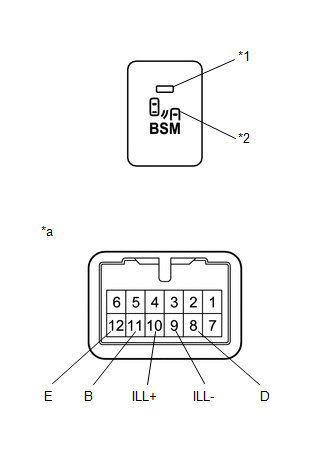
(b) Check that the blind spot monitor main switch indicates.
(1) Apply battery voltage to the blind spot monitor main switch indicator terminals.
OK:
|
Tester Connection |
Switch Condition |
Specified Condition |
|---|---|---|
|
Battery positive (+) → Terminal 11 (B) Battery negative (-) → Terminal 12 (E) |
Blind Spot Monitor Main Switch Assembly on |
Indicator Illumination |
If the result is not as specified, replace the blind spot monitor main switch.
(c) Check that the blind spot monitor main switch illuminates.
(1) Apply battery voltage to the blind spot monitor main switch illumination terminals.
OK:
|
Measurement Condition |
Specified Condition |
|---|---|
|
Battery positive (+) → Terminal 10 (ILL+) Battery negative (-) → Terminal 9 (ILL-) |
Illuminates |
If the result is not as specified, replace the blind spot monitor main switch.
|
|
|