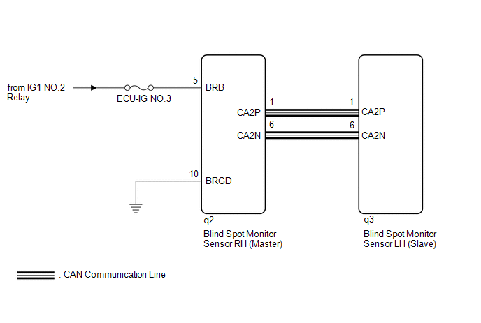
- CAN communication Line
- Blind spot monitor sensor LH
- Blind spot monitor sensor RH
| Last Modified: 08-28-2024 | 6.11:8.1.0 | Doc ID: RM100000000VJB4 |
| Model Year Start: 2016 | Model: Sienna | Prod Date Range: [12/2015 - 11/2017] |
| Title: PARK ASSIST / MONITORING: BLIND SPOT MONITOR SYSTEM: U0232; Lost Communication with Blind Spot Monitor Slave Module; 2016 - 2017 MY Sienna [12/2015 - 11/2017] | ||
|
DTC |
U0232 |
Lost Communication with Blind Spot Monitor Slave Module |
DESCRIPTION
This DTC is stored when the blind spot monitor sensor RH judges that there is a communication problem with the blind spot monitor sensor LH.
|
DTC No. |
DTC Detection Condition |
Trouble Area |
|---|---|---|
|
U0232 |
The blind spot monitor sensor RH cannot receive signals from the blind spot monitor sensor LH. |
|
WIRING DIAGRAM
CAUTION / NOTICE / HINT
NOTICE:
- When checking for DTCs, make sure that the blind spot monitor main switch (warning canceling switch assembly) is on.
- Inspect the fuses for circuits related to this system before performing the following procedure.
PROCEDURE
|
1. |
CHECK HARNESS AND CONNECTOR (BLIND SPOT MONITOR SENSOR RH - BLINDSPOT MONITOR SENSOR LH) |
(a) Disconnect the q2 blind spot monitor sensor RH connector.
(b) Disconnect the q3 blind spot monitor sensor LH connector.
(c) Measure the resistance according to the value(s) in the table below.
Standard Resistance:
|
Tester Connection |
Condition |
Specified Condition |
|---|---|---|
|
q2-1 (CA2P) - q3-1 (CA2P) |
Always |
Below 1 Ω |
|
q2-6 (CA2N) - q3-6 (CA2N) |
Always |
Below 1 Ω |
| NG |

|
REPAIR OR REPLACE CAN LINE ORCONNECTOR |
|

|
2. |
CHECK HARNESS AND CONNECTOR (POWER SOURCE TERMINAL) |
|
(a) Disconnect the blind spot monitor sensor RH connector. |
|
(b) Measure the voltage according to the value(s) in the table below.
Standard Voltage:
|
Tester Connection |
Switch Condition |
Specified Condition |
|---|---|---|
|
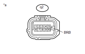
q2-5 (BRB) - Body ground |
Ignition switch ON |
11 to 14 V |
Text in Illustration
|
*a |
Front view of wire harness connector (to Blind Spot Monitor Sensor RH) |
| NG |
|
REPAIR OR REPLACE HARNESS OR CONNECTOR |
|
|
3. |
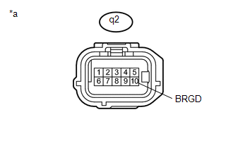
CHECK HARNESS AND CONNECTOR (GROUND TERMINAL) |
|
(a) Measure the resistance according to the value(s) in the table below. Standard Resistance:
Text in Illustration
|
|
| NG |
|
REPAIR OR REPLACE HARNESS OR CONNECTOR |
|
|
4. |
REPLACE BLIND SPOT MONITOR SENSOR RH |
(a) Replace the blind spot monitor sensor RH (See page
![2016 - 2017 MY Sienna [12/2015 - 11/2017]; PARK ASSIST / MONITORING: BLIND SPOT MONITOR SENSOR: REMOVAL](/t3Portal/stylegraphics/info.gif) ).
).
|
|
5. |
CHECK DTC |
(a) Clear the DTCs (See page
).
(b) Recheck for DTCs and check if the same DTC is output again.
OK:
No DTCs are output.
| OK |
|
END (BLIND SPOT MONITOR SENSOR RH WAS DEFECTIVE) |
| NG |
|
|
|
|