| Last Modified: 08-28-2024 | 6.11:8.1.0 | Doc ID: RM100000000VJAI |
| Model Year Start: 2016 | Model: Sienna | Prod Date Range: [12/2015 - 11/2017] |
| Title: PARK ASSIST / MONITORING: BLIND SPOT MONITOR SYSTEM: Main Switch Circuit; 2016 - 2017 MY Sienna [12/2015 - 11/2017] | ||
|
Main Switch Circuit |
DESCRIPTION
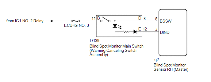
When the blind spot monitor main switch (warning canceling switch assembly) is turned on, a signal is sent to the blind spot monitor sensor LH and the blind spot monitor indicator on the blind spot monitor main switch (warning canceling switch assembly) illuminates. The blind spot monitor system operates according to this signal.
WIRING DIAGRAM
CAUTION / NOTICE / HINT
NOTICE:
Inspect the fuse for circuits related to this system before performing the following inspection procedure.
PROCEDURE
|
1. |
CHECK BLIND SPOT MONITOR MAIN SWITCH (WARNING CANCELING SWITCH ASSEMBLY) |
(a) Check that the blind spot monitor indicator on the blind spot monitor main switch (warning canceling switch assembly) illuminates normally when the blind spot monitor main switch (warning canceling switch assembly) is turned from off to on.
(b) Check that the blind spot monitor indicator on the blind spot monitor main switch (warning canceling switch assembly) turns off normally when the blind spot monitor main switch (warning canceling switch assembly) is turned from on to off.
OK:
The blind spot monitor indicator operates normally.
| OK |

|
PROCEED TO NEXT SUSPECTED AREA SHOWN IN PROBLEM SYMPTOMS TABLE (See page
|
|

|
2. |
READ VALUE USING TECHSTREAM (MAIN SWITCH) |
(a) Connect the Techstream to the DLC3.
(b) Turn the ignition switch to ON.
(c) Turn the Techstream on.
(d) Enter the following menus: Body Electrical / Blind spot monitor Master / Data list.
(e) According to the display on the Techstream, read the Data List.
Blind Spot Monitor Master
|
Tester Display |
Measurement Item/Range |
Normal Condition |
Diagnostic Note |
|---|---|---|---|
|
Main Switch |
Blind spot monitor main switch (warning canceling switch assembly) / OFF or ON |
ON: Blind spot monitor main switch (warning canceling switch assembly) on OFF: Blind spot monitor main switch (warning canceling switch assembly) off |
- |
Result
|
Result |
Proceed to |
|---|---|
|
The display does not change as shown above when the blind spot monitor main switch (warning canceling switch assembly) is operated. |
A |
|
The display changes as shown above when the blind spot monitor main switch (warning canceling switch assembly) is operated. |
B |
| B |
|
|
|
3. |
INSPECT BLIND SPOT MONITOR MAIN SWITCH (WARNING CANCELING SWITCH ASSEMBLY) |
(a) Inspect the blind spot monitor main switch (warning canceling switch assembly) (See page
![2016 - 2017 MY Sienna [12/2015 - 11/2017]; PARK ASSIST / MONITORING: BLIND SPOT MONITOR MAIN SWITCH: INSPECTION](/t3Portal/stylegraphics/info.gif) ).
).
| NG |
|
REPLACE BLIND SPOT MONITOR MAIN SWITCH (WARNING CANCELING SWITCH ASSEMBLY) |
|
|
4. |
CHECK HARNESS AND CONNECTOR (BLIND SPOT MONITOR MAIN SWITCH (WARNING CANCELING SWITCH ASSEMBLY) - BATTERY) |
|
(a) Disconnect the blind spot monitor main switch (warning canceling switch assembly) connector. |
|
(b) Measure the voltage according to the value(s) in the table below.
Standard Voltage:
|
Tester Connection |
Switch Condition |
Specified Condition |
|---|---|---|
|
D139-11 (B) - Body ground |
Ignition switch ON |
11 to 14 V |
|
D139-11 (B) - Body ground |
Ignition switch off |
Below 1 V |
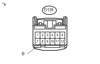
Text in Illustration
|
*a |
Front view of wire harness connector (to Blind Spot Monitor Main Switch (Warning Canceling Switch Assembly)) |
| NG |
|
REPAIR OR REPLACE HARNESS OR CONNECTOR |
|
|
5. |
CHECK HARNESS AND CONNECTOR (BLIND SPOT MONITOR MAIN SWITCH (WARNING CANCELING SWITCH ASSEMBLY - BLIND SPOT MONITOR SENSOR RH) |
(a) Disconnect the q2 blind spot monitor sensor RH connector.
(b) Disconnect the D139 blind spot monitor main switch (warning canceling switch assembly) connector.
(c) Measure the resistance according to the value(s) in the table below.
Standard Resistance:
|
Tester Connection |
Condition |
Specified Condition |
|---|---|---|
|
q2-8 (BSSW) - D139-8 (D) |
Always |
Below 1 Ω |
|
q2-8 (BSSW) - Body ground |
Always |
10 kΩ or higher |
| OK |
|
| NG |
|
REPAIR OR REPLACE HARNESS OR CONNECTOR |
|
6. |
INSPECT BLIND SPOT MONITOR MAIN SWITCH (WARNING CANCELING SWITCH ASSEMBLY) |
(a) Inspect the blind spot monitor main switch (warning canceling switch assembly) (See page
).
HINT:
Check the blind spot monitor indicator.
| NG |
|
REPLACE BLIND SPOT MONITOR MAIN SWITCH (WARNING CANCELING SWITCH ASSEMBLY) |
|
|
7. |
CHECK HARNESS AND CONNECTOR (BLIND SPOT MONITOR MAIN SWITCH (WARNING CANCELING SWITCH ASSEMBLY - BLIND SPOT MONITOR SENSOR RH) |
(a) Disconnect the q2 blind spot monitor sensor RH connector.
(b) Disconnect the D139 blind spot monitor main switch (warning canceling switch assembly) connector.
(c) Measure the resistance according to the value(s) in the table below.
Standard Resistance:
|
Tester Connection |
Condition |
Specified Condition |
|---|---|---|
|
q2-3 (BIND) - D139-12 (E) |
Always |
Below 1 Ω |
|
q2-3 (BIND) - Body ground |
Always |
10 kΩ or higher |
| OK |
|
| NG |
|
REPAIR OR REPLACE HARNESS OR CONNECTOR |
|
|
|