| Last Modified: 08-28-2024 | 6.11:8.1.0 | Doc ID: RM100000000VJAH |
| Model Year Start: 2016 | Model: Sienna | Prod Date Range: [12/2015 - ] |
| Title: PARK ASSIST / MONITORING: BLIND SPOT MONITOR SYSTEM: Power Source Circuit; 2016 - 2020 MY Sienna [12/2015 - ] | ||
|
Power Source Circuit |
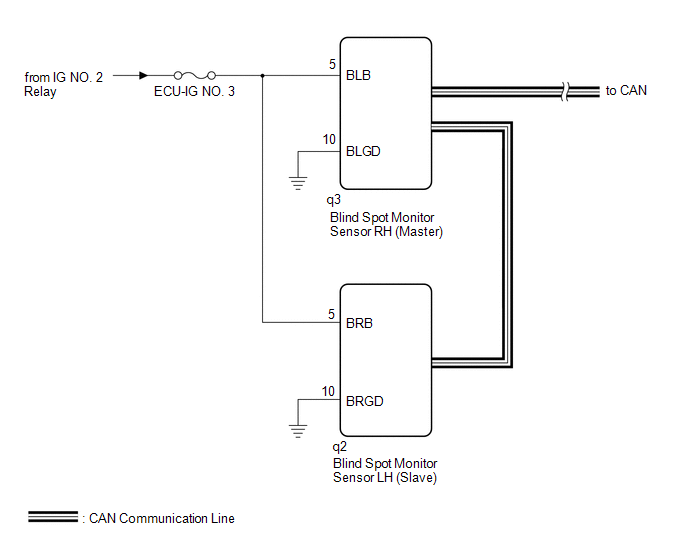
DESCRIPTION
This circuit provides power to operate the blind spot monitor sensors.
WIRING DIAGRAM
CAUTION / NOTICE / HINT
NOTICE:
Inspect the fuses for circuits related to this system before performing the following inspection procedure.
PROCEDURE
|
1. |
CHECK HARNESS AND CONNECTOR (BLIND SPOT MONITOR SENSOR RH - BATTERY) |
|
(a) Disconnect the blind spot monitor sensor RH connector. |
|
(b) Measure the voltage according to the value(s) in the table below.
Standard Voltage:
|
Tester Connection |
Switch Condition |
Specified Condition |
|---|---|---|
|
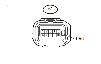
q2-5 (BRB) - Body ground |
Ignition switch ON |
11 to 14 V |
|
q2-5 (BRB) - Body ground |
Ignition switch off |
Below 1 V |
Text in Illustration
|
*a |
Front view of wire harness connector (to Blind Spot Monitor Sensor RH) |
| NG |

|
REPAIR OR REPLACE HARNESS OR CONNECTOR |
|

|
2. |
CHECK HARNESS AND CONNECTOR (BLIND SPOT MONITOR SENSOR RH - BODY GROUND) |
|
(a) Disconnect the blind spot monitor sensor RH connector. |
|
(b) Measure the resistance according to the value(s) in the table below.
Standard Resistance:
|
Tester Connection |
Condition |
Specified Condition |
|---|---|---|
|
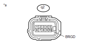
q2-10 (BRGD) - Body ground |
Always |
Below 1 Ω |
Text in Illustration
|
*a |
Front view of wire harness connector (to Blind Spot Monitor Sensor RH) |
| NG |
|
REPAIR OR REPLACE HARNESS OR CONNECTOR |
|
|
3. |
CHECK HARNESS AND CONNECTOR (BLIND SPOT MONITOR SENSOR LH - BATTERY) |
|
(a) Disconnect the blind spot monitor sensor LH connector. |
|
(b) Measure the voltage according to the value(s) in the table below.
Standard Voltage:
|
Tester Connection |
Switch Condition |
Specified Condition |
|---|---|---|
|
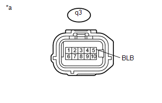
q3-5 (BLB) - Body ground |
Ignition switch ON |
11 to 14 V |
|
q3-5 (BLB) - Body ground |
Ignition switch off |
Below 1 V |
Text in Illustration
|
*a |
Front view of wire harness connector (to Blind Spot Monitor Sensor RH) |
| NG |
|
REPAIR OR REPLACE HARNESS OR CONNECTOR |
|
|
4. |
CHECK HARNESS AND CONNECTOR (BLIND SPOT MONITOR SENSOR LH - BODY GROUND) |
|
(a) Disconnect the blind spot monitor sensor LH connector. |
|
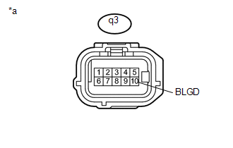
(b) Measure the resistance according to the value(s) in the table below.
Standard Resistance:
|
Tester Connection |
Condition |
Specified Condition |
|---|---|---|
|
q3-10 (BLGD) - Body ground |
Always |
Below 1 Ω |
Text in Illustration
|
*a |
Front view of wire harness connector (to Blind Spot Monitor Sensor RH) |
| OK |
|
PROCEED TO NEXT SUSPECTED AREA SHOWN IN PROBLEM SYMPTOMS TABLE (See page
|
![2016 MY Sienna [12/2015 - 08/2016]; PARK ASSIST / MONITORING: BLIND SPOT MONITOR SYSTEM: PROBLEM SYMPTOMS TABLE](/t3Portal/stylegraphics/info.gif)
| NG |
|
REPAIR OR REPLACE HARNESS OR CONNECTOR |
|
|
|