| Last Modified: 08-28-2024 | 6.11:8.1.0 | Doc ID: RM100000000VJ7W |
| Model Year Start: 2016 | Model: Sienna | Prod Date Range: [12/2015 - 11/2017] |
| Title: NAVIGATION / MULTI INFO DISPLAY: NAVIGATION SYSTEM: Data Signal Circuit between Navigation Receiver Assembly and Extension Module; 2016 - 2017 MY Sienna [12/2015 - 11/2017] | ||
|
Data Signal Circuit between Navigation Receiver Assembly and Extension Module |
DESCRIPTION
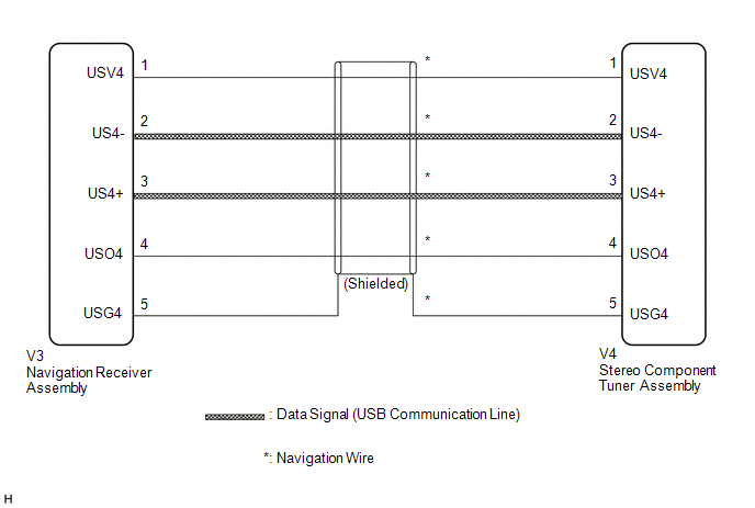
The stereo component tuner assembly sends the image data signal to the navigation receiver assembly via this circuit.
WIRING DIAGRAM
PROCEDURE
|
1. |
CHECK NAVIGATION WIRE |
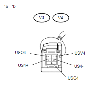
(a) Disconnect the navigation receiver assembly connector.
(b) Disconnect the stereo component tuner assembly connector.
|
(c) Measure the resistance according to the value(s) in the table below. Standard Resistance:
Text in Illustration
|
|
| OK |

|
PROCEED TO NEXT SUSPECTED AREA SHOWN IN PROBLEM SYMPTOMS TABLE (See page
|
![2016 MY Sienna [12/2015 - 08/2016]; NAVIGATION / MULTI INFO DISPLAY: NAVIGATION SYSTEM: PROBLEM SYMPTOMS TABLE](/t3Portal/stylegraphics/info.gif)
| NG |
|
|
|
|