- Video signal (digital) is lost
- Stereo component tuner assembly is/was not connected while the ignition switch is/was ACC or ON
- Communication between the navigation receiver assembly and the stereo component tuner assembly is/was not possible when the engine is/was started
| Last Modified: 08-28-2024 | 6.11:8.1.0 | Doc ID: RM100000000VJ7V |
| Model Year Start: 2016 | Model: Sienna | Prod Date Range: [12/2015 - 11/2017] |
| Title: NAVIGATION / MULTI INFO DISPLAY: NAVIGATION SYSTEM: B1532; LVDS Signal Malfunction (from Extension Module); 2016 - 2017 MY Sienna [12/2015 - 11/2017] | ||
|
DTC |
B1532 |
LVDS Signal Malfunction (from Extension Module) |
DESCRIPTION
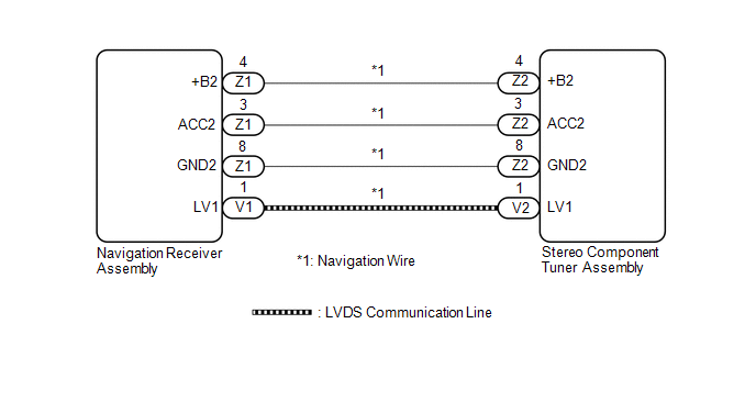
The stereo component tuner assembly and the navigation receiver assembly are connected by the LVDS communication line.
This DTC is stored when an LVDS communication error occurs between the stereo component tuner assembly and the navigation receiver assembly.
|
DTC No. |
DTC Detection Condition |
Trouble Area |
|---|---|---|
|
B1532 |
When one of the conditions below is met: |
|
HINT:
Even if no malfunction is present, this DTC may be stored depending on the battery condition or engine start voltage.
WIRING DIAGRAM
CAUTION / NOTICE / HINT
NOTICE:
After replacing the stereo component tuner assembly of vehicles subscribed to pay-type satellite radio broadcasts, XM radio ID registration is necessary.
PROCEDURE
|
1. |
CHECK NAVIGATION WIRE (STEREO COMPONENT TUNER ASSEMBLY POWER SOURCE) |
(a) Disconnect the Z2 stereo component tuner assembly connector.
(b) Measure the resistance according to the value(s) in the table below.
Standard Resistance:
|
Tester Connection |
Condition |
Specified Condition |
|---|---|---|
|
Z2-8 (GND2) - Body ground |
Always |
Below 1 Ω |
(c) Measure the voltage according to the value(s) in the table below.
Standard Voltage:
|
Tester Connection |
Switch Condition |
Specified Condition |
|---|---|---|
|
Z2-4 (+B2) - Z2-8 (GND2) |
Ignition switch ON |
11 to 14 V |
|
Z2-3 (ACC2) - Z2-8 (GND2) |
Ignition switch ACC |
11 to 14 V |
| NG |

|
|

|
2. |
REPLACE NAVIGATION WIRE |
(a) Replace the navigation wire with a new or known good one (See page
![2016 - 2017 MY Sienna [12/2015 - 11/2017]; NAVIGATION / MULTI INFO DISPLAY: NAVIGATION RECEIVER: REMOVAL](/t3Portal/stylegraphics/info.gif) ).
).
(b) Clear the DTCs (See page
).
(c) Recheck for DTCs and check that no DTCs are output.
OK:
No DTCs are output.
| OK |
|
END (NAVIGATION WIRE WAS DEFECTIVE) |
|
|
3. |
REPLACE STEREO COMPONENT TUNER ASSEMBLY |
(a) Replace the stereo component tuner assembly with a new or known good one (See page
).
(b) Clear the DTCs (See page
).
(c) Recheck for DTCs and check that no DTCs are output.
OK:
No DTCs are output.
| OK |
|
END (STEREO COMPONENT TUNER ASSEMBLY WAS DEFECTIVE) |
| NG |
|
|
4. |
CHECK NAVIGATION WIRE |
(a) Disconnect the Z1 navigation receiver assembly connector.
(b) Disconnect the Z2 stereo component tuner assembly connector.
(c) Measure the resistance according to the value(s) in the table below.
Standard Resistance:
|
Tester Connection |
Condition |
Specified Condition |
|---|---|---|
|
Z1-4 (+B2) - Z2-4 (+B2) |
Always |
Below 1 Ω |
|
Z1-3 (ACC2) - Z2-3 (ACC2) |
Always |
Below 1 Ω |
|
Z1-8 (GND2) - Z2-8 (GND2) |
Always |
Below 1 Ω |
|
Z1-4 (+B2) - Body ground |
Always |
10 kΩ or higher |
|
Z1-3 (ACC2) - Body ground |
Always |
10 kΩ or higher |
|
Z1-8 (GND2) - Body ground |
Always |
10 kΩ or higher |
| OK |
|
| NG |
|
|
|
|