- Navigation receiver assembly
- Harness or connector
| Last Modified: 08-28-2024 | 6.11:8.1.0 | Doc ID: RM100000000VJ7S |
| Model Year Start: 2016 | Model: Sienna | Prod Date Range: [12/2015 - 11/2017] |
| Title: NAVIGATION / MULTI INFO DISPLAY: NAVIGATION SYSTEM: B158F; AV Signal Stoppage (Low Battery Voltage); 2016 - 2017 MY Sienna [12/2015 - 11/2017] | ||
|
DTC |
B158F |
AV Signal Stoppage (Low Battery Voltage) |
DESCRIPTION
This DTC is stored when a video or audio signal is interrupted due to battery voltage input to the navigation receiver assembly dropping temporarily.
|
DTC No. |
DTC Detection Condition |
Trouble Area |
|---|---|---|
|
B158F |
A video or audio signal is interrupted when the battery voltage drops |
|
WIRING DIAGRAM
CAUTION / NOTICE / HINT
NOTICE:
Inspect the fuses for circuits related to this system before performing the following inspection procedure.
PROCEDURE
|
1. |
CHECK VEHICLE SIGNAL (OPERATION CHECK) |
|
(a) Enter the "Vehicle Signal Check Mode" screen. Refer to Check Vehicle Signal in Operation Check (See page
|
|
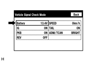
(b) Check the battery voltage.
Standard Voltage:
11 to 14 V
HINT:
This display is updated once per second.
| NG |

|
|

|
2. |
CHECK DTC |
(a) Clear the DTCs (See page
![2016 - 2017 MY Sienna [12/2015 - 11/2017]; NAVIGATION / MULTI INFO DISPLAY: NAVIGATION SYSTEM: DTC CHECK / CLEAR](/t3Portal/stylegraphics/info.gif) ).
).
(b) Recheck for DTCs and check that no DTCs are output.
OK:
No DTCs are output.
| OK |
|
USE SIMULATION METHOD TO CHECK (See page
|
| NG |
|
|
3. |
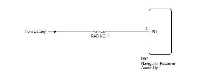
CHECK HARNESS AND CONNECTOR (NAVIGATION RECEIVER ASSEMBLY POWER SOURCE) |
|
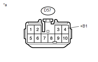
(a) Disconnect the navigation receiver assembly connector. |
|
(b) Measure the voltage according to the value(s) in the table below.
Standard Voltage:
|
Tester Connection |
Condition |
Specified Condition |
|---|---|---|
|
D57-4 (+B1) - Body ground |
Always |
11 to 14 V |
Text in Illustration
|
*a |
Front view of wire harness connector (to Navigation Receiver Assembly) |
| OK |
|
| NG |
|
REPAIR OR REPLACE HARNESS OR CONNECTOR |
|
|
|