- Amplifier microphone assembly
- DCM (telematics transceiver)*1
- Navigation receiver assembly
- Harness or connector
| Last Modified: 08-28-2024 | 6.11:8.1.0 | Doc ID: RM100000000VJ7K |
| Model Year Start: 2016 | Model: Sienna | Prod Date Range: [12/2015 - 11/2017] |
| Title: NAVIGATION / MULTI INFO DISPLAY: NAVIGATION SYSTEM: B1579; Voice Recognition Microphone Disconnected; 2016 - 2017 MY Sienna [12/2015 - 11/2017] | ||
|
DTC |
B1579 |
Voice Recognition Microphone Disconnected |
DESCRIPTION
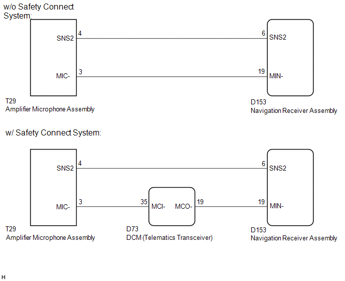
The navigation receiver assembly and amplifier microphone assembly are connected to each other using the microphone connection detection signal lines.
This DTC is stored when a microphone connection detection signal line is disconnected.
|
DTC Code |
DTC Detection Condition |
Trouble Area |
|---|---|---|
|
B1579 |
Microphone signal is lost |
|
- *1: w/ Safety Connect System
WIRING DIAGRAM
CAUTION / NOTICE / HINT
NOTICE:
If the DCM (telematics transceiver) has been replaced, perform the DCM Activation procedure using the Techstream (w/ Safety Connect System) (See page
![2016 MY Sienna [12/2015 - 08/2016]; INTRODUCTION: REPAIR INSTRUCTION: INITIALIZATION](/t3Portal/stylegraphics/info.gif) ).
).
PROCEDURE
|
1. |
INSPECT NAVIGATION RECEIVER ASSEMBLY |
|
(a) Measure the resistance according to the value(s) in the table below. Standard Resistance:
Text in Illustration
|
|
| NG |

|
|

|
2. |
CONFIRM MODEL |
(a) Choose the model to be inspected.
Result
|
Result |
Proceed to |
|---|---|
|
w/ Safety Connect System |
A |
|
w/o Safety Connect System |
B |
| B |
|
|
|
3. |
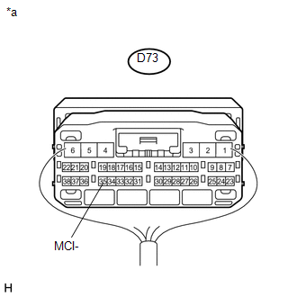
CHECK HARNESS AND CONNECTOR (DCM (TELEMATICS TRANSCEIVER) - AMPLIFIER MICROPHONE ASSEMBLY) |
(a) Disconnect the D73 DCM (telematics transceiver) connector.
(b) Disconnect the T29 amplifier microphone assembly connector.
(c) Measure the resistance according to the value(s) in the table below.
Standard Resistance:
|
Tester Connection |
Condition |
Specified Condition |
|---|---|---|
|
D73-35 (MCI-) - T29-3 (MIC-) |
Always |
Below 1 Ω |
|
D73-35 (MCI-) - Body ground |
Always |
10 kΩ or higher |
| NG |
|
REPAIR OR REPLACE HARNESS OR CONNECTOR |
|
|
4. |
CHECK HARNESS AND CONNECTOR (NAVIGATION RECEIVER ASSEMBLY - DCM (TELEMATICS TRANSCEIVER)) |
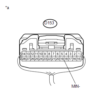
(a) Disconnect the D153 navigation receiver assembly connector.
(b) Disconnect the D73 DCM (telematics transceiver) connector.
(c) Measure the resistance according to the value(s) in the table below.
Standard Resistance:
|
Tester Connection |
Condition |
Specified Condition |
|---|---|---|
|
D153-19 (MIN-) - D73-19 (MCO-) |
Always |
Below 1 Ω |
|
D153-19 (MIN-) - Body ground |
Always |
10 kΩ or higher |
| NG |
|
REPAIR OR REPLACE HARNESS OR CONNECTOR |
|
|
5. |
CHECK HARNESS AND CONNECTOR (NAVIGATION RECEIVER ASSEMBLY - AMPLIFIER MICROPHONE ASSEMBLY) |
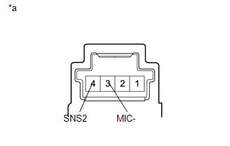
(a) Disconnect the D153 navigation receiver assembly connector.
(b) Disconnect the T29 amplifier microphone assembly connector.
(c) Measure the resistance according to the value(s) in the table below.
Standard Resistance:
|
Tester Connection |
Condition |
Specified Condition |
|---|---|---|
|
D153-6 (SNS2) - T29-4 (SNS2) |
Always |
Below 1 Ω |
|
D153-6 (SNS2) - Body ground |
Always |
10 kΩ or higher |
| NG |
|
REPAIR OR REPLACE HARNESS OR CONNECTOR |
|
|
6. |
INSPECT DCM (TELEMATICS TRANSCEIVER) |
|
(a) Measure the resistance according to the value(s) in the table below. Standard Resistance:
|
|
Result
|
Result |
Proceed to |
|---|---|
|
NG |
A |
|
OK |
B |
Text in Illustration
|
*a |
Component with harness connected (DCM (Telematics Transceiver)) |
| A |
|
| B |
|
|
7. |
CHECK HARNESS AND CONNECTOR (NAVIGATION RECEIVER ASSEMBLY - AMPLIFIER MICROPHONE ASSEMBLY) |
(a) Disconnect the D153 navigation receiver assembly connector.
(b) Disconnect the T29 amplifier microphone assembly connector.
(c) Measure the resistance according to the value(s) in the table below.
Standard Resistance:
|
Tester Connection |
Condition |
Specified Condition |
|---|---|---|
|
D153-6 (SNS2) - T29-4 (SNS2) |
Always |
Below 1 Ω |
|
D153-19 (MIN-) - T29-3 (MIC-) |
Always |
Below 1 Ω |
|
D153-6 (SNS2) - Body ground |
Always |
10 kΩ or higher |
|
D153-19 (MIN-) - Body ground |
Always |
10 kΩ or higher |
| NG |
|
REPAIR OR REPLACE HARNESS OR CONNECTOR |
|
|
8. |
INSPECT AMPLIFIER MICROPHONE ASSEMBLY |
(a) Remove the amplifier microphone assembly (See page
).
|
(b) Measure the resistance according to the value(s) in the table below. Standard Resistance:
Text in Illustration
|
|
| OK |
|
| NG |
|
|
|
|