- Antenna cord sub-assembly
- No. 2 antenna cord sub-assembly (roof headlining assembly)
- Telephone antenna assembly
- Stereo component tuner assembly
| Last Modified: 08-28-2024 | 6.11:8.1.0 | Doc ID: RM100000000VJ7E |
| Model Year Start: 2016 | Model: Sienna | Prod Date Range: [12/2015 - 11/2017] |
| Title: NAVIGATION / MULTI INFO DISPLAY: NAVIGATION SYSTEM: B15FE,B15FF; XM Tuner Antenna Disconnected; 2016 - 2017 MY Sienna [12/2015 - 11/2017] | ||
|
DTC |
B15FE |
XM Tuner Antenna Disconnected |
|
DTC |
B15FF |
XM Tuner Antenna Short |
DESCRIPTION
These DTCs are stored when a malfunction occurs in the roof antenna assembly which is connected to the stereo component tuner assembly.
|
DTC No. |
DTC Detection Condition |
Trouble Area |
|---|---|---|
|
B15FE |
The roof antenna assembly is not connected |
|
|
B15FF |
A short occurs in the roof antenna assembly |
CAUTION / NOTICE / HINT
NOTICE:
- Some satellite radio broadcasts require payment. A contract must be made between a satellite radio company and the user. If the contract expires, it will not be possible to listen to the broadcast.
- After replacing the stereo component tuner assembly of vehicles subscribed to pay-type satellite radio broadcasts, XM radio ID registration is necessary.
PROCEDURE
|
1. |
CHECK CONNECTION OF SATELLITE RADIO ANTENNA CABLE |
(a) Check if the satellite radio antenna cable is securely connected to the stereo component tuner assembly.
OK:
Satellite radio antenna cable is securely connected.
| NG |

|
SECURELY CONNECT SATELLITE RADIOANTENNA CABLE |
|

|
2. |
INSPECT ANTENNA CORD SUB-ASSEMBLY |
(a) Disconnect the antenna cord sub-assembly connector from the stereo component tuner assembly.
(b) Disconnect the antenna cord sub-assembly connector from the No. 2 antenna cord sub-assembly.
|
(c) Measure the resistance according to the value(s) in the table below. Standard Resistance:
|
|
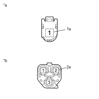
Text in Illustration
|
*a |
Front view of wire harness connector (to Stereo Component Tuner Assembly) |
|
*b |
Front view of wire harness connector (to No. 2 Antenna Cord Sub-assembly) |
| NG |
|
|
|
3. |
INSPECT NO. 2 ANTENNA CORD SUB-ASSEMBLY (ROOF HEADLINING ASSEMBLY) |
(a) Disconnect the No. 2 antenna cord sub-assembly (roof headlining assembly) connector from the antenna cord sub-assembly.
(b) Disconnect the No. 2 antenna cord sub-assembly (roof headlining assembly) connector from the telephone antenna assembly.
|
(c) Measure the resistance according to the value(s) in the table below. Standard Resistance:
|
|
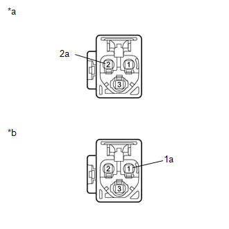
Text in Illustration
|
*a |
Front view of wire harness connector (to Antenna Cord Sub-assembly) |
|
*b |
Front view of wire harness connector (to Telephone Antenna Assembly) |
| NG |
|
|
|
4. |
REPLACE TELEPHONE ANTENNA ASSEMBLY |
(a) Replace the telephone antenna assembly with a known good one (See page
![2016 - 2017 MY Sienna [12/2015 - 11/2017]; AUDIO / VIDEO: SATELLITE RADIO ANTENNA: REMOVAL](/t3Portal/stylegraphics/info.gif) ).
).
(b) Clear the DTCs (See page
).
(c) Recheck for DTCs and check that no DTCs are output.
OK:
No DTCs are output.
| OK |
|
END (TELEPHONE ANTENNA ASSEMBLY WAS DEFECTIVE) |
| NG |
|
|
|
|