- The stereo component amplifier assembly is/was not connected while the ignition switch is/was ACC or ON
- Communication between the master unit and the stereo component amplifier assembly is not possible when the engine is started
| Last Modified: 08-28-2024 | 6.11:8.1.0 | Doc ID: RM100000000VJ74 |
| Model Year Start: 2016 | Model: Sienna | Prod Date Range: [12/2015 - 11/2017] |
| Title: NAVIGATION / MULTI INFO DISPLAY: NAVIGATION SYSTEM: B15D3; Stereo Component Amplifier Disconnected; 2016 - 2017 MY Sienna [12/2015 - 11/2017] | ||
|
DTC |
B15D3 |
Stereo Component Amplifier Disconnected |
DESCRIPTION
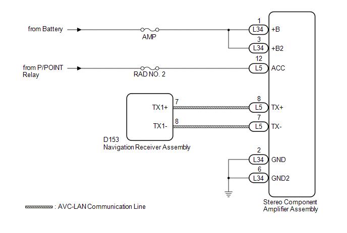
The navigation receiver assembly and stereo component amplifier assembly are connected by the AVC-LAN communication line.
This DTC is stored when an AVC-LAN communication error occurs between the navigation receiver assembly and stereo component amplifier assembly.
|
DTC No. |
DTC Detection Condition |
Trouble Area |
|---|---|---|
|
B15D3 |
When either condition below is met: |
|
HINT:
The navigation receiver assembly is the master unit.
WIRING DIAGRAM
CAUTION / NOTICE / HINT
NOTICE:
Inspect the fuses for circuits related to this system before performing the following inspection procedure.
PROCEDURE
|
1. |
CHECK DTC |
(a) If DTC B15C3 is output, perform the troubleshooting for DTC B15C3 first.
Result
|
Result |
Proceed to |
|---|---|
|
DTC B15C3 is not output |
A |
|
DTC B15C3 is output |
B |
| B |

|
|

|
2. |
CHECK OPTIONAL COMPONENTS (INCLUDING ASSOCIATED WIRING) |
(a) Check that optional components (including associated wiring) which generate radio waves are not installed.
Result
|
Result |
Proceed to |
|---|---|
|
Optional components (including associated wiring) are installed |
A |
|
Optional components (including associated wiring) are not installed |
B |
HINT:
- Electrical noise from radio waves generated by optional components or the wiring for those components may affect AVC-LAN communication.
- This DTC may be stored when an AVC-LAN communication error occurs due to electrical noise.
| B |
|
|
|
3. |
REMOVE OPTIONAL COMPONENTS (INCLUDING ASSOCIATED WIRING) |
(a) Remove optional components (including associated wiring).
NOTICE:
Do not remove optional components or associated wiring without the permission of the customer.
|
|
4. |
CHECK DTC |
(a) Clear the DTCs (See page
![2016 - 2017 MY Sienna [12/2015 - 11/2017]; NAVIGATION / MULTI INFO DISPLAY: NAVIGATION SYSTEM: DTC CHECK / CLEAR](/t3Portal/stylegraphics/info.gif) ).
).
(b) Recheck for DTCs and check that no DTCs are output.
OK:
No DTCs are output.
| OK |
|
END |
|
|
5. |
CHECK HARNESS AND CONNECTOR (STEREO COMPONENT AMPLIFIER ASSEMBLY POWER SOURCE) |
(a) Disconnect the stereo component amplifier assembly connectors.
|
(b) Measure the resistance according to the value(s) in the table below. Standard Resistance:
|
|
(c) Measure the voltage according to the value(s) in the table below.
Standard Voltage:
|
Tester Connection |
Switch Condition |
Specified Condition |
|---|---|---|
|
L34-1 (+B) - L34-2 (GND) |
Always |
11 to 14 V |
|
L34-3 (+B2) - L34-2 (GND) |
Always |
11 to 14 V |
|
L5-12 (ACC) - L34-2 (GND) |
Ignition switch ACC |
11 to 14 V |
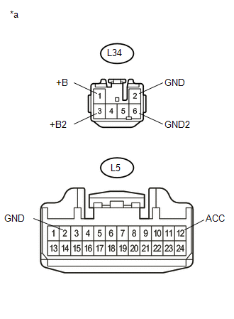
Text in Illustration
|
*a |
Front view of wire harness connector (to Stereo Component Amplifier Assembly) |
| NG |
|
REPAIR OR REPLACE HARNESS OR CONNECTOR |
|
|
6. |
CHECK HARNESS AND CONNECTOR (NAVIGATION RECEIVER ASSEMBLY - STEREO COMPONENT AMPLIFIER ASSEMBLY) |
(a) Disconnect the D153 navigation receiver assembly connector.
(b) Disconnect the L5 stereo component amplifier assembly connector.
(c) Measure the resistance according to the value(s) in the table below.
Standard Resistance:
|
Tester Connection |
Condition |
Specified Condition |
|---|---|---|
|
D153-7 (TX1+) - L5-8 (TX+) |
Always |
Below 1 Ω |
|
D153-8 (TX1-) - L5-7 (TX-) |
Always |
Below 1 Ω |
|
D153-7 (TX1+) - Body ground |
Always |
10 kΩ or higher |
|
D153-8 (TX1-) - Body ground |
Always |
10 kΩ or higher |
| NG |
|
REPAIR OR REPLACE HARNESS OR CONNECTOR |
|
|
7. |
REPLACE STEREO COMPONENT AMPLIFIER ASSEMBLY |
(a) Replace the stereo component amplifier assembly with a new or known good one (See page
).
(b) Clear the DTCs (See page
).
(c) Recheck for DTCs and check that no DTCs are output.
OK:
No DTCs are output.
| OK |
|
END (STEREO COMPONENT AMPLIFIER ASSEMBLY WAS DEFECTIVE) |
| NG |
|
|
|
|