- Harness or connector
- Speaker
- Navigation receiver assembly*1
- Stereo component amplifier assembly*2
- DCM (telematics transceiver)*3
| Last Modified: 08-28-2024 | 6.11:8.1.0 | Doc ID: RM100000000VJ73 |
| Model Year Start: 2016 | Model: Sienna | Prod Date Range: [12/2015 - 11/2017] |
| Title: NAVIGATION / MULTI INFO DISPLAY: NAVIGATION SYSTEM: B15C3; Speaker Output Short; 2016 - 2017 MY Sienna [12/2015 - 11/2017] | ||
|
DTC |
B15C3 |
Speaker Output Short |
DESCRIPTION
This DTC is stored when a malfunction occurs in the speakers.
|
DTC No. |
DTC Detection Condition |
Trouble Area |
|---|---|---|
|
B15C3 |
A short is detected in the speaker output circuit |
|
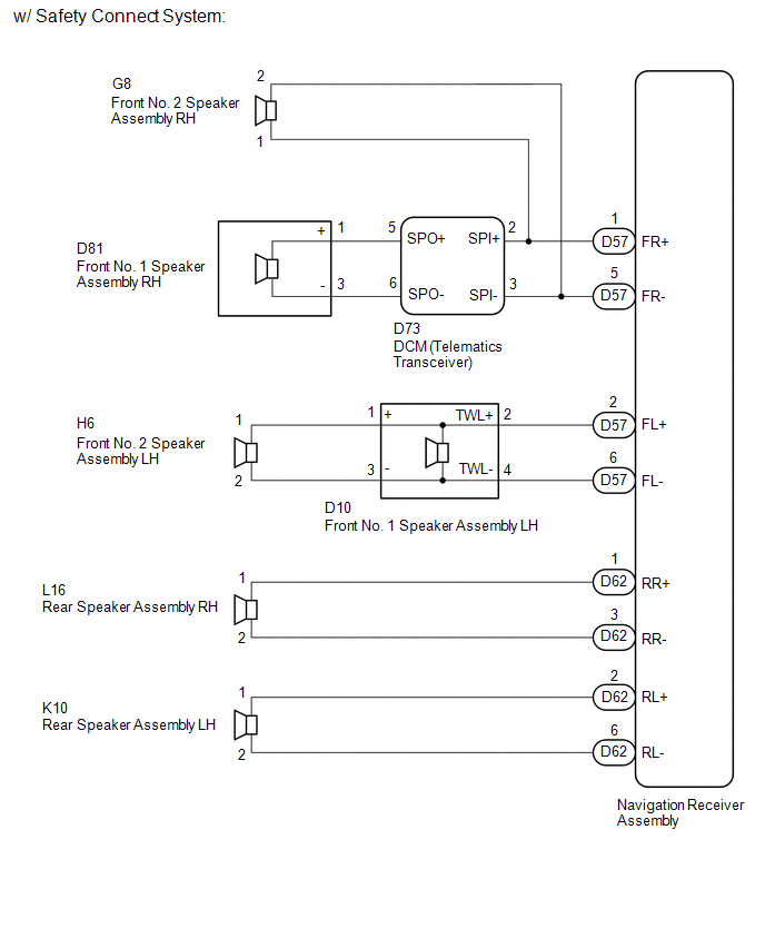
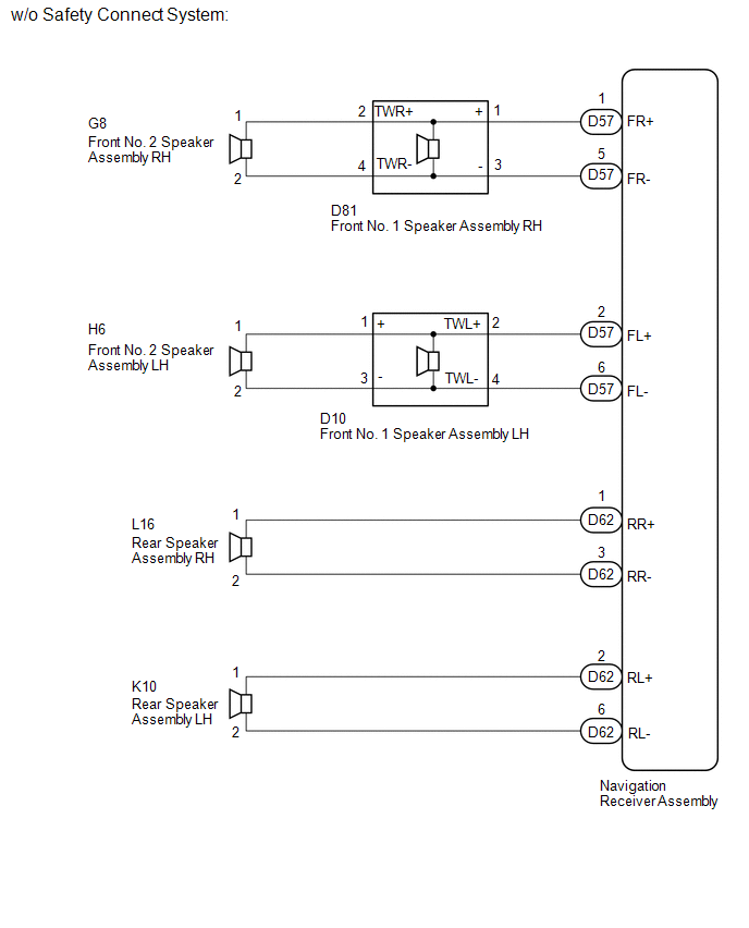
- *1: for 6 Speakers
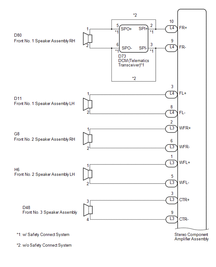
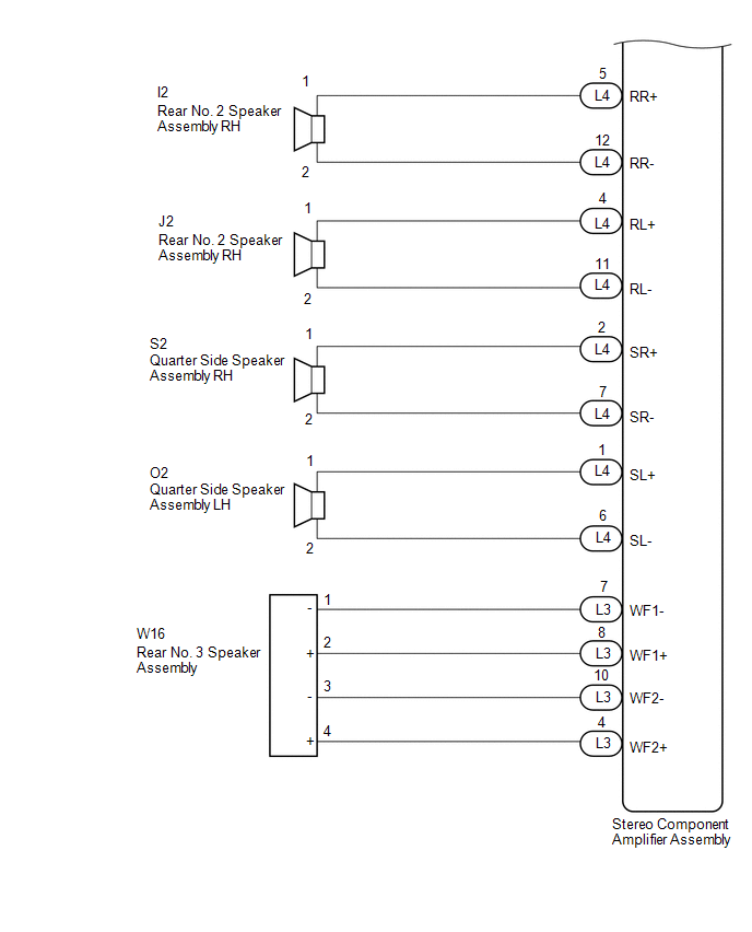
- *2: for 10 Speakers
- *3: w/ Safety Connect System
WIRING DIAGRAM
1. for 6 Speakers
2. for 10 Speakers
CAUTION / NOTICE / HINT
NOTICE:
If the DCM (telematics transceiver) has been replaced, perform the DCM Activation procedure using the Techstream (w/ Safety Connect System) (See page
![2016 - 2017 MY Sienna [12/2015 - 11/2017]; CELLULAR COMMUNICATION: SAFETY CONNECT SYSTEM: PRECAUTION](/t3Portal/stylegraphics/info.gif) ).
).
PROCEDURE
|
1. |
CONFIRM MODEL |
(a) Choose the model to be inspected.
Result
|
Result |
Proceed to |
|---|---|
|
for 6 Speakers |
A |
|
for 10 Speakers |
B |
| B |

|
|

|
2. |
CONFIRM MODEL |
(a) Choose the model to be inspected.
Result
|
Result |
Proceed to |
|---|---|
|
w/ Safety Connect System |
A |
|
w/o Safety Connect System |
B |
| B |
|
|
|
3. |
CHECK HARNESS AND CONNECTOR (NAVIGATION RECEIVER ASSEMBLY - BODY GROUND) |
(a) Disconnect the D57 and D62 navigation receiver assembly connectors.
(b) Disconnect the G8 front No. 2 speaker assembly RH connector.
(c) Disconnect the D73 DCM (telematics transceiver) connector.
(d) Disconnect the D10 front No. 1 speaker assembly LH connector.
(e) Disconnect the L16 and K10 rear speaker assembly connectors.
(f) Measure the resistance between the navigation receiver assembly and body ground to check for a short circuit in the wire harness.
Standard Resistance:
|
Tester Connection |
Condition |
Specified Condition |
|---|---|---|
|
D57-1 (FR+) - Body ground |
Always |
10 kΩ or higher |
|
D57-5 (FR-) - Body ground |
Always |
10 kΩ or higher |
|
D57-2 (FL+) - Body ground |
Always |
10 kΩ or higher |
|
D57-6 (FL-) - Body ground |
Always |
10 kΩ or higher |
|
D62-1 (RR+) - Body ground |
Always |
10 kΩ or higher |
|
D62-3 (RR-) - Body ground |
Always |
10 kΩ or higher |
|
D62-2 (RL+) - Body ground |
Always |
10 kΩ or higher |
|
D62-6 (RL-) - Body ground |
Always |
10 kΩ or higher |
| NG |
|
REPAIR OR REPLACE HARNESS OR CONNECTOR |
|
|
4. |
CHECK HARNESS AND CONNECTOR (DCM (TELEMATICS TRANSCEIVER) - BODY GROUND) |
(a) Disconnect the D73 DCM (telematics transceiver) connector.
(b) Disconnect the D81 front No. 1 speaker assembly RH connector.
(c) Measure the resistance between the DCM (telematics transceiver) and body ground to check for a short circuit in the wire harness.
Standard Resistance:
|
Tester Connection |
Condition |
Specified Condition |
|---|---|---|
|
D73-5 (SPO+) - Body ground |
Always |
10 kΩ or higher |
|
D73-6 (SPO-) - Body ground |
Always |
10 kΩ or higher |
| NG |
|
REPAIR OR REPLACE HARNESS OR CONNECTOR |
|
|
5. |
CHECK HARNESS AND CONNECTOR (FRONT NO. 1 SPEAKER ASSEMBLY LH - BODY GROUND) |
(a) Disconnect the H6 front No. 2 speaker assembly LH connector.
(b) Disconnect the D10 front No. 1 speaker assembly LH connector.
(c) Measure the resistance between the front No. 1 speaker assembly and body ground to check for a short circuit in the wire harness.
Standard Resistance:
|
Tester Connection |
Condition |
Specified Condition |
|---|---|---|
|
D10-1 (+) - Body ground |
Always |
10 kΩ or higher |
|
D10-3 (-) - Body ground |
Always |
10 kΩ or higher |
| NG |
|
REPAIR OR REPLACE HARNESS OR CONNECTOR |
|
|
6. |
INSPECT DCM (TELEMATICS TRANSCEIVER) |
(a) Remove the DCM (telematics transceiver).
|
(b) Measure the resistance according to the value(s) in the table below. Standard Resistance:
Result
|
|
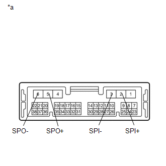
Text in Illustration
|
*a |
Component without harness connected (DCM (Telematics Transceiver)) |
| A |
|
| B |
|
|
7. |
CHECK HARNESS AND CONNECTOR (NAVIGATION RECEIVER ASSEMBLY - BODY GROUND) |
(a) Disconnect the D57 and D62 navigation receiver assembly connectors.
(b) Disconnect the D81 and D10 front No. 1 speaker assembly connectors.
(c) Disconnect the L16 and K10 rear speaker assembly connectors.
(d) Measure the resistance between the navigation receiver assembly and body ground to check for a short circuit in the wire harness.
Standard Resistance:
|
Tester Connection |
Condition |
Specified Condition |
|---|---|---|
|
D57-1 (FR+) - Body ground |
Always |
10 kΩ or higher |
|
D57-5 (FR-) - Body ground |
Always |
10 kΩ or higher |
|
D57-2 (FL+) - Body ground |
Always |
10 kΩ or higher |
|
D57-6 (FL-) - Body ground |
Always |
10 kΩ or higher |
|
D62-1 (RR+) - Body ground |
Always |
10 kΩ or higher |
|
D62-3 (RR-) - Body ground |
Always |
10 kΩ or higher |
|
D62-2 (RL+) - Body ground |
Always |
10 kΩ or higher |
|
D62-6 (RL-) - Body ground |
Always |
10 kΩ or higher |
| NG |
|
REPAIR OR REPLACE HARNESS OR CONNECTOR |
|
|
8. |
CHECK HARNESS AND CONNECTOR (FRONT NO. 1 SPEAKER ASSEMBLY - BODY GROUND) |
(a) Disconnect the G8 and H6 front No. 2 speaker assembly connectors.
(b) Disconnect the D81 and D10 front No. 1 speaker assembly connectors.
(c) Measure the resistance between each of the front No. 1 speaker assemblies and body ground to check for a short circuit in the wire harness.
Standard Resistance:
|
Tester Connection |
Condition |
Specified Condition |
|---|---|---|
|
D81-2 (TWR+) - Body ground |
Always |
10 kΩ or higher |
|
D81-4 (TWR-) - Body ground |
Always |
10 kΩ or higher |
|
D10-1 (+) - Body ground |
Always |
10 kΩ or higher |
|
D10-3 (-) - Body ground |
Always |
10 kΩ or higher |
| NG |
|
REPAIR OR REPLACE HARNESS OR CONNECTOR |
|
|
9. |
INSPECT FRONT NO. 1 SPEAKER ASSEMBLY |
(a) Remove the front No. 1 speaker assembly (See page
).
(b) Inspect the front No. 1 speaker assembly (See page
).
| NG |
|
|
|
10. |
INSPECT FRONT NO. 2 SPEAKER ASSEMBLY |
(a) Remove the front No. 2 speaker assembly (See page
).
(b) Inspect the front No. 2 speaker assembly (See page
).
| NG |
|
|
|
11. |
REPLACE FRONT NO. 2 SPEAKER ASSEMBLY |
(a) Replace the front No. 2 speaker assembly with a new or known good one (See page
).
(b) Clear the DTCs (See page
).
(c) Recheck for DTCs and check that no DTCs are output.
OK:
No DTCs are output.
HINT:
- Connect all the connectors to the front No. 2 speaker assemblies that were disconnected.
- When there is a possibility that either the right or left front No. 2 speaker assembly is defective, inspect by interchanging the right one with the left one.
- Perform the above inspection on both the LH and RH side.
Result
|
Result |
Proceed to |
|---|---|
|
DTCs are output |
A |
|
No DTCs are output |
B |
| B |
|
END |
|
|
12. |
INSPECT REAR SPEAKER ASSEMBLY |
(a) Remove the rear speaker assembly (See page
).
(b) Inspect the rear speaker assembly (See page
).
| OK |
|
| NG |
|
|
13. |
CONFIRM MODEL |
(a) Choose the model to be inspected.
Result
|
Result |
Proceed to |
|---|---|
|
w/ Safety Connect System |
A |
|
w/o Safety Connect System |
B |
| B |
|
|
|
14. |
CHECK HARNESS AND CONNECTOR (STEREO COMPONENT AMPLIFIER ASSEMBLY - BODY GROUND) |
(a) Disconnect the L3 and L4 stereo component amplifier assembly connectors.
(b) Disconnect the D73 DCM (telematics transceiver) connector.
(c) Disconnect the G8 and H6 front No. 2 speaker assembly connectors.
(d) Disconnect the D11 front No. 1 speaker assembly LH connector.
(e) Disconnect the D48 front No. 3 speaker assembly connector.
(f) Disconnect the I2 and J2 rear No. 2 speaker assembly connectors.
(g) Disconnect the O2 and S2 quarter side speaker assembly connectors.
(h) Disconnect the W16 rear No. 3 speaker assembly connector.
(i) Measure the resistance between the stereo component amplifier assembly and body ground to check for a short circuit in the wire harness.
Standard Resistance:
|
Tester Connection |
Condition |
Specified Condition |
|---|---|---|
|
L4-10 (FR+) - Body ground |
Always |
10 kΩ or higher |
|
L4-9 (FR-) - Body ground |
Always |
10 kΩ or higher |
|
L4-3 (FL+) - Body ground |
Always |
10 kΩ or higher |
|
L4-8 (FL-) - Body ground |
Always |
10 kΩ or higher |
|
L4-5 (RR+) - Body ground |
Always |
10 kΩ or higher |
|
L4-12 (RR-) - Body ground |
Always |
10 kΩ or higher |
|
L4-4 (RL+) - Body ground |
Always |
10 kΩ or higher |
|
L4-11 (RL-) - Body ground |
Always |
10 kΩ or higher |
|
L4-2 (SR+) - Body ground |
Always |
10 kΩ or higher |
|
L4-7 (SR-) - Body ground |
Always |
10 kΩ or higher |
|
L4-1 (SL+) - Body ground |
Always |
10 kΩ or higher |
|
L4-6 (SL-) - Body ground |
Always |
10 kΩ or higher |
|
L3-3 (CTR+) - Body ground |
Always |
10 kΩ or higher |
|
L3-9 (CTR+) - Body ground |
Always |
10 kΩ or higher |
|
L3-2 (WFR+) - Body ground |
Always |
10 kΩ or higher |
|
L3-6 (WFR-) - Body ground |
Always |
10 kΩ or higher |
|
L3-1 (WFL+) - Body ground |
Always |
10 kΩ or higher |
|
L3-5 (WFL-) - Body ground |
Always |
10 kΩ or higher |
|
L3-8 (WF1+) - Body ground |
Always |
10 kΩ or higher |
|
L3-7 (WF1-) - Body ground |
Always |
10 kΩ or higher |
|
L3-4 (WF2+) - Body ground |
Always |
10 kΩ or higher |
|
L3-10 (WF2-) - Body ground |
Always |
10 kΩ or higher |
| NG |
|
REPAIR OR REPLACE HARNESS OR CONNECTOR |
|
|
15. |
CHECK HARNESS AND CONNECTOR (DCM (TELEMATICS TRANSCEIVER) - BODY GROUND) |
(a) Disconnect the D73 DCM (telematics transceiver) connector.
(b) Disconnect the D80 front No. 1 speaker assembly RH connector.
(c) Measure the resistance between the DCM (telematics transceiver) and body ground to check for a short circuit in the wire harness.
Standard Resistance:
|
Tester Connection |
Condition |
Specified Condition |
|---|---|---|
|
D73-5 (SPO+) - Body ground |
Always |
10 kΩ or higher |
|
D73-6 (SPO-) - Body ground |
Always |
10 kΩ or higher |
| NG |
|
REPAIR OR REPLACE HARNESS OR CONNECTOR |
|
|
16. |
INSPECT DCM (TELEMATICS TRANSCEIVER) |
(a) Remove the DCM (telematics transceiver) (See page
).
|
(b) Measure the resistance according to the value(s) in the table below. Standard Resistance:
|
|
Result
|
Result |
Proceed to |
|---|---|
|
NG |
A |
|
OK |
B |
Text in Illustration
|
*a |
Component without harness connected (DCM (Telematics Transceiver)) |
| A |
|
| B |
|
|
17. |
CHECK HARNESS AND CONNECTOR (STEREO COMPONENT AMPLIFIER ASSEMBLY - BODY GROUND) |
(a) Disconnect the L3 and L4 stereo component amplifier assembly connectors.
(b) Disconnect the G8 and H6 front No. 2 speaker assembly connectors.
(c) Disconnect the D11 and D80 front No. 1 speaker assembly connectors.
(d) Disconnect the D48 front No. 3 speaker assembly connector.
(e) Disconnect the I2 and J2 rear No. 2 speaker assembly connectors.
(f) Disconnect the O2 and S2 quarter side speaker assembly connectors.
(g) Disconnect the W16 rear No. 3 speaker assembly connector.
(h) Measure the resistance between the stereo component amplifier assembly and body ground to check for a short circuit in the wire harness.
Standard Resistance:
|
Tester Connection |
Condition |
Specified Condition |
|---|---|---|
|
L4-10 (FR+) - Body ground |
Always |
10 kΩ or higher |
|
L4-9 (FR-) - Body ground |
Always |
10 kΩ or higher |
|
L4-3 (FL+) - Body ground |
Always |
10 kΩ or higher |
|
L4-8 (FL-) - Body ground |
Always |
10 kΩ or higher |
|
L4-5 (RR+) - Body ground |
Always |
10 kΩ or higher |
|
L4-12 (RR-) - Body ground |
Always |
10 kΩ or higher |
|
L4-4 (RL+) - Body ground |
Always |
10 kΩ or higher |
|
L4-11 (RL-) - Body ground |
Always |
10 kΩ or higher |
|
L4-2 (SR+) - Body ground |
Always |
10 kΩ or higher |
|
L4-7 (SR-) - Body ground |
Always |
10 kΩ or higher |
|
L4-1 (SL+) - Body ground |
Always |
10 kΩ or higher |
|
L4-6 (SL-) - Body ground |
Always |
10 kΩ or higher |
|
L3-3 (CTR+) - Body ground |
Always |
10 kΩ or higher |
|
L3-9 (CTR+) - Body ground |
Always |
10 kΩ or higher |
|
L3-2 (WFR+) - Body ground |
Always |
10 kΩ or higher |
|
L3-6 (WFR-) - Body ground |
Always |
10 kΩ or higher |
|
L3-1 (WFL+) - Body ground |
Always |
10 kΩ or higher |
|
L3-5 (WFL-) - Body ground |
Always |
10 kΩ or higher |
|
L3-8 (WF1+) - Body ground |
Always |
10 kΩ or higher |
|
L3-7 (WF1-) - Body ground |
Always |
10 kΩ or higher |
|
L3-4 (WF2+) - Body ground |
Always |
10 kΩ or higher |
|
L3-10 (WF2-) - Body ground |
Always |
10 kΩ or higher |
| NG |
|
REPAIR OR REPLACE HARNESS OR CONNECTOR |
|
|
18. |
INSPECT FRONT NO. 1 SPEAKER ASSEMBLY |
(a) Remove the front No. 1 speaker assembly (See page
).
(b) Inspect the front No. 1 speaker assembly (See page
).
| NG |
|
|
|
19. |
INSPECT FRONT NO. 2 SPEAKER ASSEMBLY |
(a) Remove the front No. 2 speaker assembly (See page
).
(b) Inspect the front No. 2 speaker assembly (See page
).
| NG |
|
|
|
20. |
INSPECT FRONT NO. 3 SPEAKER ASSEMBLY |
(a) Remove the front No. 3 speaker assembly (See page
).
(b) Inspect the front No. 3 speaker assembly (See page
).
| NG |
|
|
|
21. |
INSPECT REAR NO. 2 SPEAKER ASSEMBLY |
(a) Remove the rear No. 2 speaker assembly (See page
).
(b) Inspect the rear No. 2 speaker assembly (See page
).
| NG |
|
|
|
22. |
INSPECT QUARTER SIDE SPEAKER ASSEMBLY |
(a) Remove the quarter side speaker assembly (See page
).
(b) Inspect the quarter side speaker assembly (See page
).
| NG |
|
|
|
23. |
INSPECT REAR NO. 3 SPEAKER ASSEMBLY |
(a) Remove the rear No. 3 speaker assembly (See page
).
(b) Inspect the rear No. 3 speaker assembly (See page
).
| OK |
|
| NG |
|
|
|
|