| Last Modified: 08-28-2024 | 6.11:8.1.0 | Doc ID: RM100000000VJ6W |
| Model Year Start: 2016 | Model: Sienna | Prod Date Range: [12/2015 - 11/2017] |
| Title: NAVIGATION / MULTI INFO DISPLAY: NAVIGATION SYSTEM: Mute Signal Circuit between Navigation Receiver Assembly and Stereo Component Amplifier; 2016 - 2017 MY Sienna [12/2015 - 11/2017] | ||
|
Mute Signal Circuit between Navigation Receiver Assembly and Stereo Component Amplifier |
DESCRIPTION
This circuit sends a signal to the stereo component amplifier assembly to mute noise. Due to this, the noise produced by changing the sound source ceases.
If there is an open in the circuit, noise can be heard from the speakers when changing the sound source.
If there is a short in the circuit, even though the stereo component amplifier assembly is functioning normally, no sound or only an extremely faint sound can be heard.
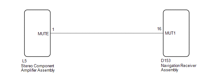
WIRING DIAGRAM
PROCEDURE
|
1. |
INSPECT STEREO COMPONENT AMPLIFIER ASSEMBLY |
|
(a) Measure the voltage according to the value(s) in the table below. Standard Voltage:
Text in Illustration
|
|
| OK |

|
PROCEED TO NEXT SUSPECTED AREA SHOWN IN PROBLEM SYMPTOMS TABLE (See page
|
![2016 MY Sienna [12/2015 - 08/2016]; NAVIGATION / MULTI INFO DISPLAY: NAVIGATION SYSTEM: PROBLEM SYMPTOMS TABLE](/t3Portal/stylegraphics/info.gif)
|

|
2. |
CHECK HARNESS AND CONNECTOR (NAVIGATION RECEIVER ASSEMBLY - STEREO COMPONENT AMPLIFIER ASSEMBLY) |
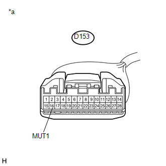
(a) Disconnect the D153 navigation receiver assembly connector.
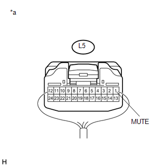
(b) Disconnect the L5 stereo component amplifier assembly connector.
(c) Measure the resistance according to the value(s) in the table below.
Standard Resistance:
|
Tester Connection |
Condition |
Specified Condition |
|---|---|---|
|
D153-16 (MUT1) - L5-1 (MUTE) |
Always |
Below 1 Ω |
|
D153-16 (MUT1) - Body ground |
Always |
10 kΩ or higher |
| NG |
|
REPAIR OR REPLACE HARNESS OR CONNECTOR |
|
|
3. |
INSPECT STEREO COMPONENT AMPLIFIER ASSEMBLY |
(a) Disconnect the navigation receiver assembly connector.
|
(b) Measure the voltage according to the value(s) in the table below. Standard Voltage:
Text in Illustration
|
|
| OK |
|
| NG |
|
|
|
|