| Last Modified: 08-28-2024 | 6.11:8.1.0 | Doc ID: RM100000000VJ6S |
| Model Year Start: 2016 | Model: Sienna | Prod Date Range: [12/2015 - 11/2017] |
| Title: NAVIGATION / MULTI INFO DISPLAY: NAVIGATION SYSTEM: Microphone Circuit between Microphone and Navigation Receiver Assembly; 2016 - 2017 MY Sienna [12/2015 - 11/2017] | ||
|
Microphone Circuit between Microphone and Navigation Receiver Assembly |
DESCRIPTION
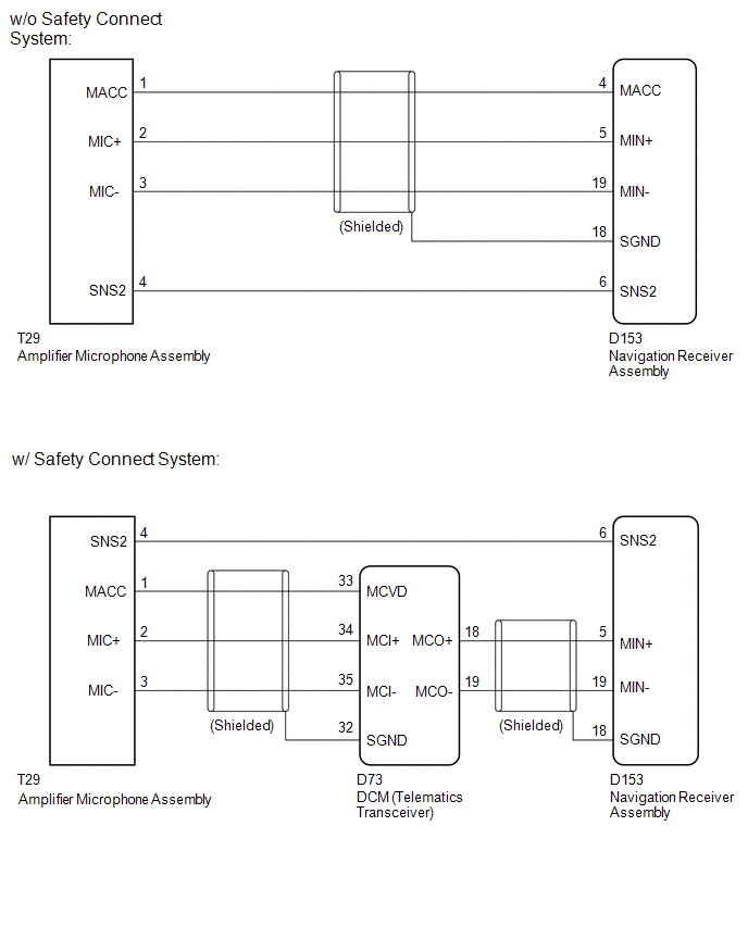
w/o Safety Connect System:
The navigation receiver assembly and amplifier microphone assembly are connected to each other using the microphone connection detection signal lines.
Using this circuit, the navigation receiver assembly sends power to the amplifier microphone assembly, and the amplifier microphone assembly sends microphone signals to the navigation receiver assembly.
w/ Safety Connect System:
The navigation receiver assembly and amplifier microphone assembly are connected to each other using the microphone connection detection signal lines.
Using this circuit, the DCM (telematics transceiver) sends power to the amplifier microphone assembly, and the amplifier microphone assembly sends microphone signals to the navigation receiver assembly via the DCM (telematics transceiver).
WIRING DIAGRAM
CAUTION / NOTICE / HINT
NOTICE:
If the DCM (telematics transceiver) has been replaced, perform the DCM Activation procedure using the Techstream (w/ Safety Connect System) (See page
![2016 MY Sienna [12/2015 - 08/2016]; INTRODUCTION: REPAIR INSTRUCTION: INITIALIZATION](/t3Portal/stylegraphics/info.gif) ).
).
PROCEDURE
|
1. |
CHECK MICROPHONE (OPERATION CHECK) |
|
(a) Enter the "Microphone Check" screen. Refer to Check Microphone in Operation Check (See page
|
|
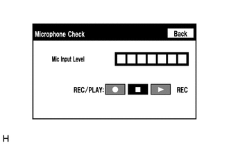
(b) When a voice is input into the microphone, check that the microphone input level meter changes according to the input voice.
(c) Push the recording switch and perform voice recording.
HINT:
- Select the recording switch with the blower motor of the air conditioning system stopped. If an outlet of the air conditioning system is facing the microphone, noise may be recorded.
- Voice can be recorded for up to 5 seconds.
(d) Check that the recording indicator remains on while recording and that the recorded voice is played normally without noise or distortion.
OK:
All check results are normal.
| OK |

|
PROCEED TO NEXT SUSPECTED AREA SHOWN IN PROBLEM SYMPTOMS TABLE (See page
|
|

|
2. |
CONFIRM MODEL |
(a) Choose the model to be inspected.
Result
|
Result |
Proceed to |
|---|---|
|
w/o Safety Connect System |
A |
|
w/ Safety Connect System |
B |
| B |
|
|
|
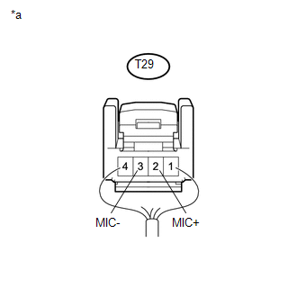
3. |
CHECK HARNESS AND CONNECTOR (NAVIGATION RECEIVER ASSEMBLY - AMPLIFIER MICROPHONE ASSEMBLY) |
(a) Disconnect the D153 navigation receiver assembly connector.
(b) Disconnect the T29 amplifier microphone assembly connector.
(c) Measure the resistance according to the value(s) in the table below.
Standard Resistance:
|
Tester Connection |
Condition |
Specified Condition |
|---|---|---|
|
D153-4 (MACC) - T29-1 (MACC) |
Always |
Below 1 Ω |
|
D153-5 (MIN+) - T29-2 (MIC+) |
Always |
Below 1 Ω |
|
D153-19 (MIN-) - T29-3 (MIC-) |
Always |
Below 1 Ω |
|
D153-6 (SNS2) - T29-4 (SNS2) |
Always |
Below 1 Ω |
|
D153-4 (MACC) - Body ground |
Always |
10 kΩ or higher |
|
D153-5 (MIN+) - Body ground |
Always |
10 kΩ or higher |
|
D153-19 (MIN-) - Body ground |
Always |
10 kΩ or higher |
|
D153-18 (SGND) - Body ground |
Always |
10 kΩ or higher |
|
D153-6 (SNS2) - Body ground |
Always |
10 kΩ or higher |
| NG |
|
REPAIR OR REPLACE HARNESS OR CONNECTOR |
|
|
4. |
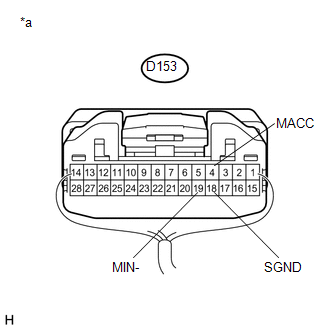
INSPECT NAVIGATION RECEIVER ASSEMBLY |
|
(a) Measure the voltage according to the value(s) in the table below. Standard Voltage:
|
|
(b) Measure the resistance according to the value(s) in the table below.
Standard Resistance:
|
Tester Connection |
Condition |
Specified Condition |
|---|---|---|
|
D153-18 (SGND) - Body ground |
Always |
Below 1 Ω |
|
D153-19 (MIN-) - Body ground |
Always |
Below 1 Ω |
Result
|
Result |
Proceed to |
|---|---|
|
NG |
A |
|
OK |
B |
Text in Illustration
|
*a |
Component with harness connected (Navigation Receiver Assembly) |
| A |
|
| B |
|
|
5. |
CHECK HARNESS AND CONNECTOR (NAVIGATION RECEIVER ASSEMBLY - AMPLIFIER MICROPHONE ASSEMBLY) |
(a) Disconnect the D153 navigation receiver assembly connector.
(b) Disconnect the T29 amplifier microphone assembly connector.
(c) Measure the resistance according to the value(s) in the table below.
Standard Resistance:
|
Tester Connection |
Condition |
Specified Condition |
|---|---|---|
|
D153-6 (SNS2) - T29-4 (SNS2) |
Always |
Below 1 Ω |
|
D153-6 (SNS2) - Body ground |
Always |
10 kΩ or higher |
| NG |
|
REPAIR OR REPLACE HARNESS OR CONNECTOR |
|
|
6. |
CHECK HARNESS AND CONNECTOR (NAVIGATION RECEIVER ASSEMBLY - DCM (TELEMATICS TRANSCEIVER)) |
(a) Disconnect the D153 navigation receiver assembly connector.
(b) Disconnect the D73 DCM (telematics transceiver) connector.
(c) Measure the resistance according to the value(s) in the table below.
Standard Resistance:
|
Tester Connection |
Condition |
Specified Condition |
|---|---|---|
|
D153-5 (MIN+) - D73-18 (MCO+) |
Always |
Below 1 Ω |
|
D153-19 (MIN-) - D73-19 (MCO-) |
Always |
Below 1 Ω |
|
D153-5 (MIN+) - Body ground |
Always |
10 kΩ or higher |
|
D153-19 (MIN-) - Body ground |
Always |
10 kΩ or higher |
|
D153-18 (SGND) - Body ground |
Always |
10 kΩ or higher |
| NG |
|
REPAIR OR REPLACE HARNESS OR CONNECTOR |
|
|
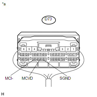
7. |
CHECK HARNESS AND CONNECTOR (DCM (TELEMATICS TRANSCEIVER) - AMPLIFIER MICROPHONE ASSEMBLY) |
(a) Disconnect the D73 DCM (telematics transceiver) connector.
(b) Disconnect the T29 amplifier microphone assembly connector.
(c) Measure the resistance according to the value(s) in the table below.
Standard Resistance:
|
Tester Connection |
Condition |
Specified Condition |
|---|---|---|
|
D73-33 (MCVD) - T29-1 (MACC) |
Always |
Below 1 Ω |
|
D73-34 (MCI+) - T29-2 (MIC+) |
Always |
Below 1 Ω |
|
D73-35 (MCI-) - T29-3 (MIC-) |
Always |
Below 1 Ω |
|
D73-33 (MCVD) - Body ground |
Always |
10 kΩ or higher |
|
D73-34 (MCI+) - Body ground |
Always |
10 kΩ or higher |
|
D73-35 (MCI-) - Body ground |
Always |
10 kΩ or higher |
|
D73-32 (SGND) - Body ground |
Always |
10 kΩ or higher |
| NG |
|
REPAIR OR REPLACE HARNESS OR CONNECTOR |
|
|
8. |
INSPECT NAVIGATION RECEIVER ASSEMBLY |
|
(a) Disconnect the D73 DCM (telematics transceiver) connector. |
|
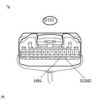
(b) Measure the resistance according to the value(s) in the table below.
Standard Resistance:
|
Tester Connection |
Condition |
Specified Condition |
|---|---|---|
|
D153-18 (SGND) - Body ground |
Always |
Below 1 Ω |
|
D153-19 (MIN-) - Body ground |
Always |
Below 1 Ω |
Text in Illustration
|
*a |
Component with harness connected (Navigation Receiver Assembly) |
| NG |
|
|
|
9. |
INSPECT DCM (TELEMATICS TRANSCEIVER) |
|
(a) Measure the voltage according to the value(s) in the table below. Standard Voltage:
|
|
(b) Measure the resistance according to the value(s) in the table below.
Standard Resistance:
|
Tester Connection |
Condition |
Specified Condition |
|---|---|---|
|
D73-35 (MCI-) - Body ground |
Always |
Below 1 Ω |
|
D73-32 (SGND) - Body ground |
Always |
Below 1 Ω |
Text in Illustration
|
*a |
Component with harness connected (DCM (Telematics Transceiver)) |
| NG |
|
|
|
10. |
INSPECT AMPLIFIER MICROPHONE ASSEMBLY |
(a) Remove the amplifier microphone assembly (See page
).
|
(b) Measure the resistance according to the value(s) in the table below. Standard Resistance:
Text in Illustration
|
|
| NG |
|
|
|
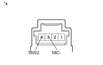
11. |
INSPECT AMPLIFIER MICROPHONE ASSEMBLY |
(a) Turn the ignition switch to ACC.
|
(b) Connect an oscilloscope to terminals 2 (MIC+) and 3 (MIC-) of the T29 amplifier microphone assembly connector. |
|
(c) Check the waveform of the amplifier microphone assembly using the oscilloscope.
Result
|
Result |
Proceed to |
|---|---|
|
A waveform synchronized with the voice input to the amplifier microphone assembly is output |
A |
|
A waveform synchronized with the voice input to the amplifier microphone assembly is not output |
B |
Text in Illustration
|
*a |
Component with harness connected (Amplifier Microphone Assembly) |
| A |
|
PROCEED TO NEXT SUSPECTED AREA SHOWN IN PROBLEM SYMPTOMS TABLE (See page
|
| B |
|
|
|
|