| Last Modified: 08-28-2024 | 6.11:8.1.0 | Doc ID: RM100000000VJ69 |
| Model Year Start: 2016 | Model: Sienna | Prod Date Range: [12/2015 - 11/2017] |
| Title: NAVIGATION / MULTI INFO DISPLAY: NAVIGATION SYSTEM: Speaker Circuit; 2016 - 2017 MY Sienna [12/2015 - 11/2017] | ||
|
Speaker Circuit |
DESCRIPTION
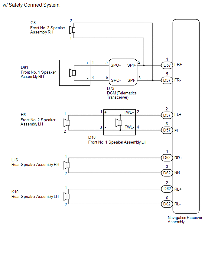
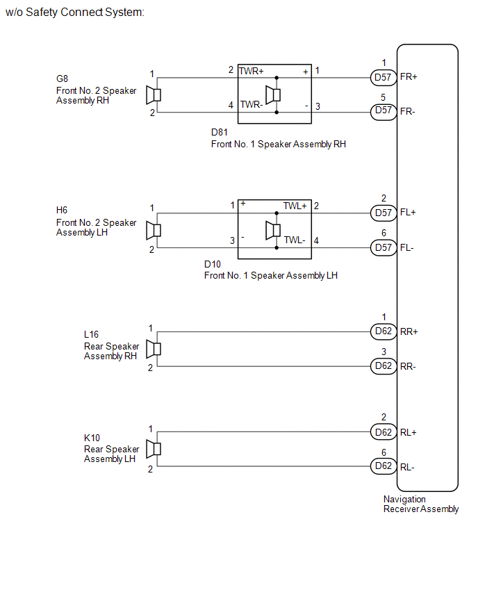
for 6 Speakers:
If there is a short in a speaker circuit, the navigation receiver assembly detects it and stops output to the speakers.
Thus sound cannot be heard from the speakers even if there is no malfunction in the navigation receiver assembly or speakers.
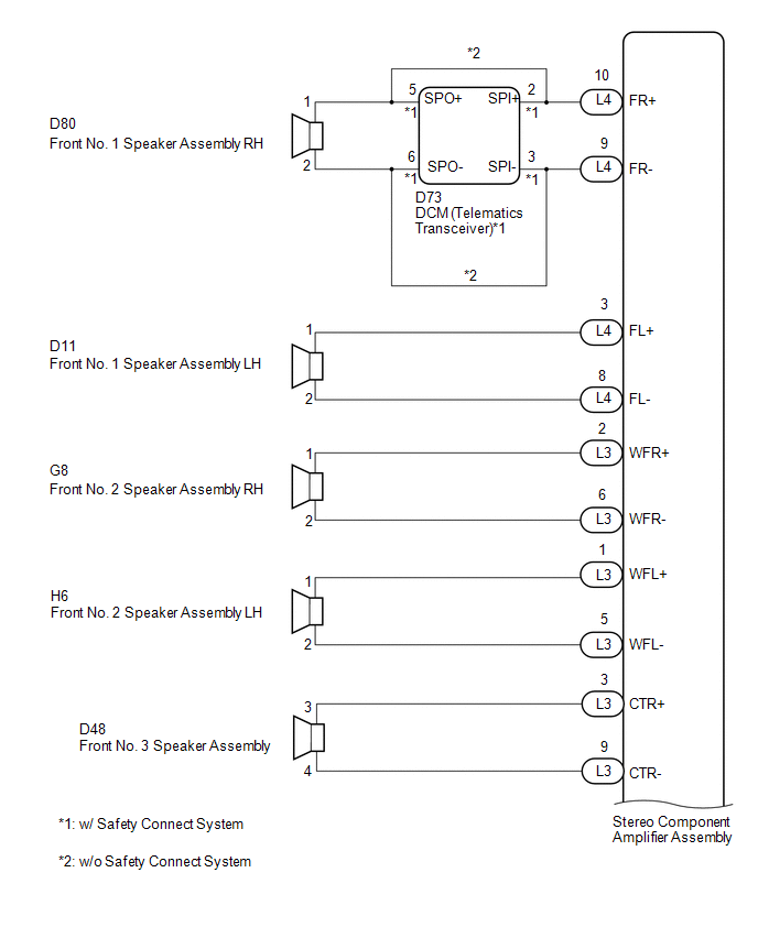
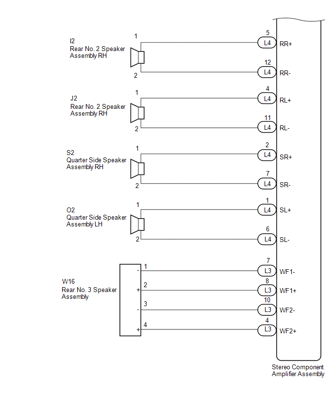
for 10 Speakers:
If there is a short in a speaker circuit, the stereo component amplifier assembly detects it and stops output to the speakers.
Thus sound cannot be heard from the speakers even if there is no malfunction in the stereo component amplifier assembly, DCM (telematics transceiver)*1 or speakers.
*1: w/ Safety Connect System
WIRING DIAGRAM
1. for 6 Speakers
2. for 10 Speakers
CAUTION / NOTICE / HINT
NOTICE:
If the DCM (telematics transceiver) has been replaced, perform the DCM Activation procedure using the Techstream (w/ Safety Connect System) (See page
![2016 MY Sienna [12/2015 - 08/2016]; INTRODUCTION: REPAIR INSTRUCTION: INITIALIZATION](/t3Portal/stylegraphics/info.gif) ).
).
PROCEDURE
|
1. |
CONFIRM MODEL |
(a) Choose the model to be inspected.
Result
|
Result |
Proceed to |
|---|---|
|
for 6 Speakers |
A |
|
for 10 Speakers |
B |
| B |

|
|

|
2. |
CHECK SPEAKER (OPERATION CHECK) |
|
(a) Enter the "System Check Mode" screen. Refer to Check Speaker in Operation Check (See page
|
|
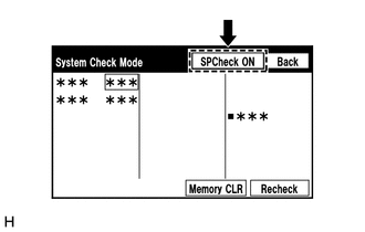
(b) Perform the operation check above and determine the speaker that is not operating.
Result
|
Not Operating Speaker |
Proceed to |
|---|---|
|
Front No. 1 speaker assembly or front No. 2 speaker assembly (w/ Safety Connect System) |
A |
|
Front No. 1 speaker assembly or front No. 2 speaker assembly (w/o Safety Connect System) |
B |
|
Rear speaker assembly |
C |
HINT:
If sound cannot be heard from any speaker, inspect all of them.
| B |
|
| C |
|
|
|
3. |
CHECK HARNESS AND CONNECTOR (NAVIGATION RECEIVER ASSEMBLY - DCM (TELEMATICS TRANSCEIVER) - FRONT NO. 2 SPEAKER ASSEMBLY RH) |
(a) Disconnect the D57 navigation receiver assembly connector.
(b) Disconnect the G8 front No. 2 speaker assembly RH connector.
(c) Disconnect the D73 DCM (telematics transceiver) connector.
(d) Measure the resistance according to the value(s) in the table below.
Standard Resistance:
|
Tester Connection |
Condition |
Specified Condition |
|---|---|---|
|
D57-1 (FR+) - D73-2 (SPI+) |
Always |
Below 1 Ω |
|
D57-5 (FR-) - D73-3 (SPI-) |
Always |
Below 1 Ω |
|
D57-1 (FR+) - G8-1 |
Always |
Below 1 Ω |
|
D57-5 (FR-) - G8-2 |
Always |
Below 1 Ω |
|
D57-1 (FR+) - Body ground |
Always |
10 kΩ or higher |
|
D57-5 (FR-) - Body ground |
Always |
10 kΩ or higher |
| NG |
|
REPAIR OR REPLACE HARNESS OR CONNECTOR |
|
|
4. |
CHECK HARNESS AND CONNECTOR (DCM (TELEMATICS TRANSCEIVER) - FRONT NO. 1 SPEAKER ASSEMBLY RH) |
(a) Disconnect the D73 DCM (telematics transceiver) connector.
(b) Disconnect the D81 front No. 1 speaker assembly RH connector.
(c) Measure the resistance according to the value(s) in the table below.
Standard Resistance:
|
Tester Connection |
Condition |
Specified Condition |
|---|---|---|
|
D73-5 (SPO+) - D81-1 (+) |
Always |
Below 1 Ω |
|
D73-6 (SPO-) - D81-3 (-) |
Always |
Below 1 Ω |
|
D73-5 (SPO+) - Body ground |
Always |
10 kΩ or higher |
|
D73-6 (SPO-) - Body ground |
Always |
10 kΩ or higher |
| NG |
|
REPAIR OR REPLACE HARNESS OR CONNECTOR |
|
|
5. |
CHECK HARNESS AND CONNECTOR (NAVIGATION RECEIVER ASSEMBLY - FRONT NO. 1 SPEAKER ASSEMBLY LH) |
(a) Disconnect the D57 navigation receiver assembly connector.
(b) Disconnect the D10 front No. 1 speaker assembly LH connector.
(c) Measure the resistance according to the value(s) in the table below.
Standard Resistance:
|
Tester Connection |
Condition |
Specified Condition |
|---|---|---|
|
D57-2 (FL+) - D10-2 (TWL+) |
Always |
Below 1 Ω |
|
D57-6 (FL-) - D10-4 (TWL-) |
Always |
Below 1 Ω |
|
D57-2 (FL+) - Body ground |
Always |
10 kΩ or higher |
|
D57-6 (FL-) - Body ground |
Always |
10 kΩ or higher |
| NG |
|
REPAIR OR REPLACE HARNESS OR CONNECTOR |
|
|
6. |
CHECK HARNESS AND CONNECTOR (FRONT NO. 1 SPEAKER ASSEMBLY LH - FRONT NO. 2 SPEAKER ASSEMBLY LH) |
(a) Disconnect the D10 front No. 1 speaker assembly LH connector.
(b) Disconnect the H6 front No. 2 speaker assembly LH connector.
(c) Measure the resistance according to the value(s) in the table below.
Standard Resistance:
|
Tester Connection |
Condition |
Specified Condition |
|---|---|---|
|
D10-1 (+) - H6-1 |
Always |
Below 1 Ω |
|
D10-3 (-) - H6-2 |
Always |
Below 1 Ω |
|
D10-1 (+) - Body ground |
Always |
10 kΩ or higher |
|
D10-3 (-) - Body ground |
Always |
10 kΩ or higher |
Result
|
Not Operating Speaker |
Proceed to |
|---|---|
|
NG |
A |
|
OK |
B |
| A |
|
REPAIR OR REPLACE HARNESS OR CONNECTOR |
| B |
|
|
7. |
CHECK HARNESS AND CONNECTOR (NAVIGATION RECEIVER ASSEMBLY - FRONT NO. 1 SPEAKER ASSEMBLY) |
(a) Disconnect the D57 navigation receiver assembly connectors.
(b) Disconnect the D81 and D10 front No. 1 speaker assembly connectors.
(c) Measure the resistance according to the value(s) in the table below.
Standard Resistance:
|
Tester Connection |
Condition |
Specified Condition |
|---|---|---|
|
D57-1 (FR+) - D81-1 (+) |
Always |
Below 1 Ω |
|
D57-5 (FR-) - D81-3 (-) |
Always |
Below 1 Ω |
|
D57-2 (FL+) - D10-2 (TWL+) |
Always |
Below 1 Ω |
|
D57-6 (FL-) - D10-4 (TWL-) |
Always |
Below 1 Ω |
|
D57-1 (FR+) - Body ground |
Always |
10 kΩ or higher |
|
D57-5 (FR-) - Body ground |
Always |
10 kΩ or higher |
|
D57-2 (FL+) - Body ground |
Always |
10 kΩ or higher |
|
D57-6 (FL-) - Body ground |
Always |
10 kΩ or higher |
| NG |
|
REPAIR OR REPLACE HARNESS OR CONNECTOR |
|
|
8. |
CHECK HARNESS AND CONNECTOR (FRONT NO. 1 SPEAKER ASSEMBLY - FRONT NO. 2 SPEAKER ASSEMBLY) |
(a) Disconnect the D81 and D10 front No. 1 speaker assembly connectors.
(b) Disconnect the H6 and G8 front No. 2 speaker assembly connectors.
(c) Measure the resistance according to the value(s) in the table below.
Standard Resistance:
|
Tester Connection |
Condition |
Specified Condition |
|---|---|---|
|
D81-2 (TWR+) - G8-1 |
Always |
Below 1 Ω |
|
D81-4 (TWR-) - G8-2 |
Always |
Below 1 Ω |
|
D10-1 (+) - H6-1 |
Always |
Below 1 Ω |
|
D10-3 (-) - H6-2 |
Always |
Below 1 Ω |
|
D81-2 (TWR+) - Body ground |
Always |
10 kΩ or higher |
|
D81-4 (TWR-) - Body ground |
Always |
10 kΩ or higher |
|
D10-1 (+) - Body ground |
Always |
10 kΩ or higher |
|
D10-3 (-) - Body ground |
Always |
10 kΩ or higher |
| NG |
|
REPAIR OR REPLACE HARNESS OR CONNECTOR |
|
|
9. |
INSPECT FRONT NO. 1 SPEAKER ASSEMBLY |
(a) Remove the front No. 1 speaker assembly (See page
).
(b) Inspect the front No. 1 speaker assembly (See page
).
| NG |
|
|
|
10. |
REPLACE FRONT NO. 1 SPEAKER ASSEMBLY |
(a) Check that the malfunction disappears when a known good speaker is installed (See page
).
OK:
Malfunction disappears.
HINT:
- Connect all the connectors to the front No. 1 speaker assemblies that were disconnected.
- When there is a possibility that either the right or left front No. 1 speaker assembly is defective, inspect by interchanging the right one with the left one.
- Perform the above inspection on both the LH and RH side.
| OK |
|
END |
|
|
11. |
INSPECT FRONT NO. 2 SPEAKER ASSEMBLY |
(a) Remove the front No. 2 speaker assembly (See page
).
(b) Inspect the front No. 2 speaker assembly (See page
).
| OK |
|
PROCEED TO NEXT SUSPECTED AREA SHOWN IN PROBLEM SYMPTOMS TABLE (See page
|
| NG |
|
|
12. |
CHECK HARNESS AND CONNECTOR (NAVIGATION RECEIVER ASSEMBLY - REAR SPEAKER ASSEMBLY) |
(a) Disconnect the D62 navigation receiver assembly connector.
(b) Disconnect the L16 and K10 rear speaker assembly connectors.
(c) Measure the resistance according to the value(s) in the table below.
Standard Resistance:
|
Tester Connection |
Condition |
Specified Condition |
|---|---|---|
|
D62-1 (RR+) - L16-1 |
Always |
Below 1 Ω |
|
D62-3 (RR-) - L16-2 |
Always |
Below 1 Ω |
|
D62-2 (RL+) - K10-1 |
Always |
Below 1 Ω |
|
D62-6 (RL-) - K10-2 |
Always |
Below 1 Ω |
|
D62-1 (RR+) - Body ground |
Always |
10 kΩ or higher |
|
D62-3 (RR-) - Body ground |
Always |
10 kΩ or higher |
|
D62-2 (RL+) - Body ground |
Always |
10 kΩ or higher |
|
D62-6 (RL-) - Body ground |
Always |
10 kΩ or higher |
| NG |
|
REPAIR OR REPLACE HARNESS OR CONNECTOR |
|
|
13. |
INSPECT REAR SPEAKER ASSEMBLY |
(a) Remove the rear speaker assembly (See page
).
(b) Inspect the rear speaker assembly (See page
).
| OK |
|
PROCEED TO NEXT SUSPECTED AREA SHOWN IN PROBLEM SYMPTOMS TABLE (See page
|
| NG |
|
|
14. |
CHECK SPEAKER (OPERATION CHECK) |
|
(a) Enter the "System Check Mode" screen. Refer to Check Speaker in Operation Check (See page
|
|
(b) Perform the operation check above and determine the speaker that is not operating.
Result
|
Not Operating Speaker |
Proceed to |
|---|---|
|
Front No. 1 speaker assembly (w/ Safety Connect System) |
A |
|
Front No. 1 speaker assembly (w/o Safety Connect System) |
B |
|
Front No. 3 speaker assembly |
C |
|
Front No. 2 speaker assembly |
D |
|
Rear No. 2 speaker assembly, quarter side speaker assembly or rear No. 3 speaker assembly |
E |
HINT:
If sound cannot be heard from any speaker, inspect all of them.
| B |
|
| C |
|
| D |
|
| E |
|
|
|
15. |
CHECK HARNESS AND CONNECTOR (STEREO COMPONENT AMPLIFIER ASSEMBLY - DCM (TELEMATICS TRANSCEIVER)) |
(a) Disconnect the L4 stereo component amplifier assembly connector.
(b) Disconnect the D73 DCM (telematics transceiver) connector.
(c) Measure the resistance according to the value(s) in the table below.
Standard Resistance:
|
Tester Connection |
Condition |
Specified Condition |
|---|---|---|
|
L4-10 (FR+) - D73-2 (SPI+) |
Always |
Below 1 Ω |
|
L4-9 (FR-) - D73-3 (SPI-) |
Always |
Below 1 Ω |
|
L4-10 (FR+) - Body ground |
Always |
10 kΩ or higher |
|
L4-9 (FR-) - Body ground |
Always |
10 kΩ or higher |
| NG |
|
REPAIR OR REPLACE HARNESS OR CONNECTOR |
|
|
16. |
CHECK HARNESS AND CONNECTOR (DCM (TELEMATICS TRANSCEIVER) - FRONT NO. 1 SPEAKER ASSEMBLY RH) |
(a) Disconnect the D73 DCM (telematics transceiver) connector.
(b) Disconnect the D80 front No. 1 speaker assembly RH connector.
(c) Measure the resistance according to the value(s) in the table below.
Standard Resistance:
|
Tester Connection |
Condition |
Specified Condition |
|---|---|---|
|
D73-5 (SPO+) - D80-1 |
Always |
Below 1 Ω |
|
D73-6 (SPO-) - D80-2 |
Always |
Below 1 Ω |
|
D73-5 (SPO+) - Body ground |
Always |
10 kΩ or higher |
|
D73-6 (SPO-) - Body ground |
Always |
10 kΩ or higher |
| NG |
|
REPAIR OR REPLACE HARNESS OR CONNECTOR |
|
|
17. |
CHECK HARNESS AND CONNECTOR (STEREO COMPONENT AMPLIFIER ASSEMBLY - FRONT NO. 1 SPEAKER ASSEMBLY LH) |
(a) Disconnect the L4 stereo component amplifier assembly connectors.
(b) Disconnect the D11 front No. 1 speaker assembly connector.
(c) Measure the resistance according to the value(s) in the table below.
Standard Resistance:
|
Tester Connection |
Condition |
Specified Condition |
|---|---|---|
|
L4-3 (FL+) - D11-1 |
Always |
Below 1 Ω |
|
L4-8 (FL-) - D11-2 |
Always |
Below 1 Ω |
|
L4-3 (FL+) - Body ground |
Always |
10 kΩ or higher |
|
L4-8 (FL-) - Body ground |
Always |
10 kΩ or higher |
| NG |
|
REPAIR OR REPLACE HARNESS OR CONNECTOR |
|
|
18. |
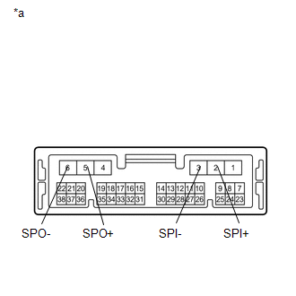
INSPECT DCM (TELEMATICS TRANSCEIVER) |
(a) Remove the DCM (telematics transceiver) (See page
).
|
(b) Measure the resistance according to the value(s) in the table below. Standard Resistance:
Text in Illustration
|
|
| NG |
|
|
|
19. |
INSPECT FRONT NO. 1 SPEAKER ASSEMBLY |
(a) Remove the front No. 1 speaker assembly (See page
).
(b) Inspect the front No. 1 speaker assembly (See page
).
| OK |
|
PROCEED TO NEXT SUSPECTED AREA SHOWN IN PROBLEM SYMPTOMS TABLE (See page
|
| NG |
|
|
20. |
CHECK HARNESS AND CONNECTOR (STEREO COMPONENT AMPLIFIER ASSEMBLY - FRONT NO. 1 SPEAKER ASSEMBLY) |
(a) Disconnect the L4 stereo component amplifier assembly connector.
(b) Disconnect the D80 and D11 front No. 1 speaker assembly connectors.
(c) Measure the resistance according to the value(s) in the table below.
Standard Resistance:
|
Tester Connection |
Condition |
Specified Condition |
|---|---|---|
|
L4-10 (FR+) - D80-1 |
Always |
Below 1 Ω |
|
L4-9 (FR-) - D80-2 |
Always |
Below 1 Ω |
|
L4-3 (FL+) - D11-1 |
Always |
Below 1 Ω |
|
L4-8 (FL-) - D11-2 |
Always |
Below 1 Ω |
|
L4-10 (FR+) - Body ground |
Always |
10 kΩ or higher |
|
L4-9 (FR-) - Body ground |
Always |
10 kΩ or higher |
|
L4-3 (FL+) - Body ground |
Always |
10 kΩ or higher |
|
L4-8 (FL-) - Body ground |
Always |
10 kΩ or higher |
| NG |
|
REPAIR OR REPLACE HARNESS OR CONNECTOR |
|
|
21. |
INSPECT FRONT NO. 1 SPEAKER ASSEMBLY |
(a) Remove the front No. 1 speaker assembly (See page
).
(b) Inspect the front No. 1 speaker assembly (See page
).
| OK |
|
PROCEED TO NEXT SUSPECTED AREA SHOWN IN PROBLEM SYMPTOMS TABLE (See page
|
| NG |
|
|
22. |
CHECK HARNESS AND CONNECTOR (STEREO COMPONENT AMPLIFIER ASSEMBLY - FRONT NO. 3 SPEAKER ASSEMBLY) |
(a) Disconnect the L3 stereo component amplifier assembly connector.
(b) Disconnect the D48 front No. 3 speaker assembly connector.
(c) Measure the resistance according to the value(s) in the table below.
Standard Resistance:
|
Tester Connection |
Condition |
Specified Condition |
|---|---|---|
|
L3-3 (CTR+) - D48-3 |
Always |
Below 1 Ω |
|
L3-9 (CTR-) - D48-4 |
Always |
Below 1 Ω |
|
L3-3 (CTR+) - Body ground |
Always |
10 kΩ or higher |
|
L3-9 (CTR-) - Body ground |
Always |
10 kΩ or higher |
| NG |
|
REPAIR OR REPLACE HARNESS OR CONNECTOR |
|
|
23. |
INSPECT FRONT NO. 3 SPEAKER ASSEMBLY |
(a) Remove the front No. 3 speaker assembly (See page
).
(b) Inspect the front No. 3 speaker assembly (See page
).
| OK |
|
PROCEED TO NEXT SUSPECTED AREA SHOWN IN PROBLEM SYMPTOMS TABLE (See page
|
| NG |
|
|
24. |
CHECK HARNESS AND CONNECTOR (STEREO COMPONENT AMPLIFIER ASSEMBLY - FRONT NO. 2 SPEAKER ASSEMBLY) |
(a) Disconnect the L3 stereo component amplifier assembly connector.
(b) Disconnect the G8 and H6 front No. 2 speaker assembly connectors.
(c) Measure the resistance according to the value(s) in the table below.
Standard Resistance:
|
Tester Connection |
Condition |
Specified Condition |
|---|---|---|
|
L3-2 (WFR+) - G8-1 |
Always |
Below 1 Ω |
|
L3-6 (WFR-) - G8-2 |
Always |
Below 1 Ω |
|
L3-1 (WFL+) - H6-1 |
Always |
Below 1 Ω |
|
L3-5 (WFL-) - H6-2 |
Always |
Below 1 Ω |
|
L3-2 (WFR+) - Body ground |
Always |
10 kΩ or higher |
|
L3-6 (WFR-) - Body ground |
Always |
10 kΩ or higher |
|
L3-1 (WFL+) - Body ground |
Always |
10 kΩ or higher |
|
L3-5 (WFL-) - Body ground |
Always |
10 kΩ or higher |
| NG |
|
REPAIR OR REPLACE HARNESS OR CONNECTOR |
|
|
25. |
INSPECT FRONT NO. 2 SPEAKER ASSEMBLY |
(a) Remove the front No. 2 speaker assembly (See page
).
(b) Inspect the front No. 2 speaker assembly (See page
).
| OK |
|
PROCEED TO NEXT SUSPECTED AREA SHOWN IN PROBLEM SYMPTOMS TABLE (See page
|
| NG |
|
|
26. |
CHECK SPEAKER (OPERATION CHECK) |
|
(a) Enter the "System Check Mode" screen. Refer to Check Speaker in Operation Check (See page
|
|
(b) Perform the operation check above and determine the speaker that is not operating.
Result
|
Not Operating Speaker |
Proceed to |
|---|---|
|
Quarter side speaker assembly |
A |
|
Rear No. 2 speaker assembly |
B |
|
Rear No. 3 speaker assembly |
C |
HINT:
If sound cannot be heard from any speaker, inspect all of them.
| B |
|
| C |
|
|
|
27. |
CHECK HARNESS AND CONNECTOR (STEREO COMPONENT AMPLIFIER ASSEMBLY - QUARTER SIDE SPEAKER ASSEMBLY) |
(a) Disconnect the L4 stereo component amplifier assembly connector.
(b) Disconnect the S2 and O2 quarter side speaker assembly connectors.
(c) Measure the resistance according to the value(s) in the table below.
Standard Resistance:
|
Tester Connection |
Condition |
Specified Condition |
|---|---|---|
|
L4-2 (SR+) - S2-1 |
Always |
Below 1 Ω |
|
L4-7 (SR-) - S2-2 |
Always |
Below 1 Ω |
|
L4-1 (SL+) - O2-1 |
Always |
Below 1 Ω |
|
L4-6 (SL-) - O2-2 |
Always |
Below 1 Ω |
|
L4-2 (SR+) - Body ground |
Always |
10 kΩ or higher |
|
L4-7 (SR-) - Body ground |
Always |
10 kΩ or higher |
|
L4-1 (SL+) - Body ground |
Always |
10 kΩ or higher |
|
L4-6 (SL-) - Body ground |
Always |
10 kΩ or higher |
| NG |
|
REPAIR OR REPLACE HARNESS OR CONNECTOR |
|
|
28. |
INSPECT QUARTER SIDE SPEAKER ASSEMBLY |
(a) Remove the quarter side speaker assembly (See page
).
(b) Inspect the quarter side speaker assembly (See page
).
| OK |
|
PROCEED TO NEXT SUSPECTED AREA SHOWN IN PROBLEM SYMPTOMS TABLE (See page
|
| NG |
|
|
29. |
CHECK HARNESS AND CONNECTOR (STEREO COMPONENT AMPLIFIER ASSEMBLY - REAR NO. 2 SPEAKER ASSEMBLY) |
(a) Disconnect the L4 stereo component amplifier assembly connector.
(b) Disconnect the I2 and J2 rear No. 2 speaker assembly connectors.
(c) Measure the resistance according to the value(s) in the table below.
Standard Resistance:
|
Tester Connection |
Condition |
Specified Condition |
|---|---|---|
|
L4-5 (RR+) - I2-1 |
Always |
Below 1 Ω |
|
L4-12 (RR-) - I2-2 |
Always |
Below 1 Ω |
|
L4-4 (RL+) - J2-1 |
Always |
Below 1 Ω |
|
L4-11 (RL-) - J2-2 |
Always |
Below 1 Ω |
|
L4-5 (RR+) - Body ground |
Always |
10 kΩ or higher |
|
L4-12 (RR-) - Body ground |
Always |
10 kΩ or higher |
|
L4-4 (RL+) - Body ground |
Always |
10 kΩ or higher |
|
L4-11 (RL-) - Body ground |
Always |
10 kΩ or higher |
| NG |
|
REPAIR OR REPLACE HARNESS OR CONNECTOR |
|
|
30. |
INSPECT REAR NO. 2 SPEAKER ASSEMBLY |
(a) Remove the rear No. 2 speaker assembly (See page
).
(b) Inspect the rear No. 2 speaker assembly (See page
).
| OK |
|
PROCEED TO NEXT SUSPECTED AREA SHOWN IN PROBLEM SYMPTOMS TABLE (See page
|
| NG |
|
|
31. |
CHECK HARNESS AND CONNECTOR (STEREO COMPONENT AMPLIFIER ASSEMBLY - REAR NO. 3 SPEAKER ASSEMBLY) |
(a) Disconnect the L3 stereo component amplifier assembly connector.
(b) Disconnect the W16 rear No. 3 speaker assembly connector.
(c) Measure the resistance according to the value(s) in the table below.
Standard Resistance:
|
Tester Connection |
Condition |
Specified Condition |
|---|---|---|
|
L3-8 (WF1+) - W16-2 (+) |
Always |
Below 1 Ω |
|
L3-7 (WF1-) - W16-1 (-) |
Always |
Below 1 Ω |
|
L3-4 (WF2+) - W16-4 (+) |
Always |
Below 1 Ω |
|
L3-10 (WF2-) - W16-3 (-) |
Always |
Below 1 Ω |
|
L3-8 (WF1+) - Body ground |
Always |
10 kΩ or higher |
|
L3-7 (WF1-) - Body ground |
Always |
10 kΩ or higher |
|
L3-4 (WF2+) - Body ground |
Always |
10 kΩ or higher |
|
L3-10 (WF2-) - Body ground |
Always |
10 kΩ or higher |
| NG |
|
REPAIR OR REPLACE HARNESS OR CONNECTOR |
|
|
32. |
INSPECT REAR NO. 3 SPEAKER ASSEMBLY |
(a) Remove the rear No. 3 speaker assembly (See page
).
(b) Inspect the rear No. 3 speaker assembly (See page
).
| OK |
|
PROCEED TO NEXT SUSPECTED AREA SHOWN IN PROBLEM SYMPTOMS TABLE (See page
|
| NG |
|
REPLACE REAR NO. 3 SPEAKER ASSEMBLY |
|
|
|