| Last Modified: 08-28-2024 | 6.11:8.1.0 | Doc ID: RM100000000VJ3R |
| Model Year Start: 2016 | Model: Sienna | Prod Date Range: [12/2015 - 11/2017] |
| Title: AUDIO / VIDEO: AUDIO AND VISUAL SYSTEM: Radio Broadcast cannot be Received (Bad Reception); 2016 - 2017 MY Sienna [12/2015 - 11/2017] | ||
|
Radio Broadcast cannot be Received (Bad Reception) |
PROCEDURE
|
1. |
CHECK IF RADIO AUTO-SEARCH FUNCTIONS PROPERLY |
(a) Check the radio automatic station search function by activating it.
OK:
Automatic station search function stops on a station.
| OK |

|
USE SIMULATION METHOD TO CHECK (See page
|
|

|
2. |
CHECK OPTIONAL COMPONENTS |
(a) Check if any optional components that may decrease reception capacity, such as sunshade film or a telephone antenna, are installed.
OK:
Optional components are installed.
NOTICE:
Do not remove optional components without permission of the customer.
| OK |
|
REMOVE OPTIONAL COMPONENTS AND CHECK AGAIN (SEE NOTICE ABOVE) |
|
|
3. |
INSPECT QUARTER WINDOW ASSEMBLY (WINDOW GLASS ANTENNA WIRE) |
(a) Inspect the quarter window assembly (window glass antenna wire) (See page
![2016 - 2020 MY Sienna [12/2015 - ]; AUDIO / VIDEO: WINDOW GLASS ANTENNA WIRE: REPAIR](/t3Portal/stylegraphics/info.gif) ).
).
| NG |
|
|
|
4. |
CHECK RADIO AND DISPLAY RECEIVER ASSEMBLY (ANTENNA) |
|
(a) Remove the antenna connector from the radio and display receiver assembly. |
|
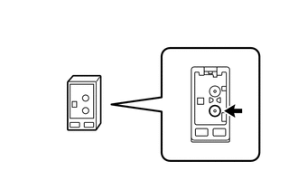
(b) Turn the ignition switch to ACC with the radio and display receiver assembly connector connected.
(c) Turn on the radio and turn into AM mode.
(d) Place a screwdriver, thin wire or other metal object on the radio and display receiver assembly antenna jack and check that noise can be heard from the speakers.
OK:
Noise occurs.
| NG |
|
|
|
5. |
INSPECT RADIO AND DISPLAY RECEIVER ASSEMBLY |
|
(a) Disconnect the RA radio and display receiver assembly connector. |
|
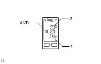
(b) Measure the voltage according to the value(s) in the table below.
Standard Voltage:
|
Tester Connection |
Switch Condition |
Specified Condition |
|---|---|---|
|
5 (ANT+) - Body ground |
Ignition switch ACC, radio switch on and FM or AM selected |
11 to 14 V |
| NG |
|
|
|
6. |
CHECK ANTENNA CORD SUB-ASSEMBLY |
|
(a) Disconnect the radio and display receiver assembly connector. |
|
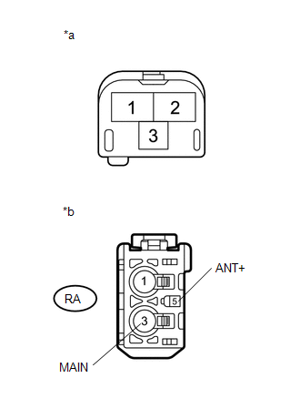
(b) Disconnect the antenna cord sub-assembly connector from the amplifier antenna assembly.
(c) Measure the resistance according to the value(s) in the table below.
Standard Resistance:
|
Tester Connection |
Condition |
Specified Condition |
|---|---|---|
|
RA-3 (MAIN) - 2 |
Always |
Below 1 Ω |
|
RA-5 (ANT+) - 3 |
Always |
Below 1 Ω |
|
RA-3 (MAIN) - Body ground |
Always |
10 kΩ or higher |
|
RA-5 (ANT+) - Body ground |
Always |
10 kΩ or higher |
Text in Illustration
|
*a |
Front view of wire harness connector (to Amplifier Antenna Assembly) |
|
*b |
Front view of wire harness connector (to Radio and Display Receiver Assembly) |
| NG |
|
REPLACE ANTENNA CORD SUB-ASSEMBLY |
|
|
7. |
CHECK NO. 2 ANTENNA CORD SUB-ASSEMBLY (ROOF HEADLINING ASSEMBLY) |
|
(a) Disconnect the No. 2 antenna cord sub-assembly (roof headlining assembly) connector from radio and display receiver assembly. |
|
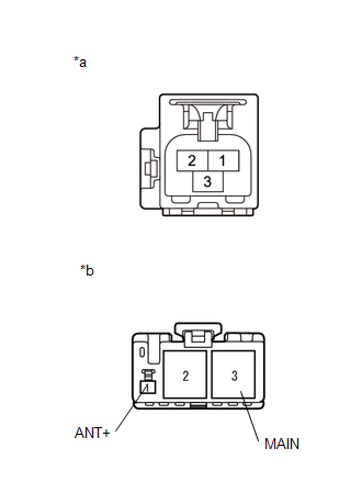
(b) Disconnect the No. 2 antenna cord sub-assembly (roof headlining assembly) connector from the amplifier antenna assembly.
(c) Measure the resistance according to the value(s) in the table below.
Standard Resistance:
|
Tester Connection |
Condition |
Specified Condition |
|---|---|---|
|
2 - 3 (MAIN) |
Always |
Below 1 Ω |
|
3 - 1 (ANT+) |
Always |
Below 1 Ω |
|
3 (MAIN) - Body ground |
Always |
10 kΩ or higher |
|
1 (ANT+) - Body ground |
Always |
10 kΩ or higher |
Text in Illustration
|
*a |
Front view of wire harness connector (to Radio and Display Receiver Assembly) |
|
*b |
Front view of wire harness connector (to Amplifier Antenna Assembly) |
| NG |
|
REPLACE ROOF HEADLINING ASSEMBLY |
|
|
8. |
CHECK GLASS ANTENNA |
|
(a) Check for continuity of the antenna. HINT: Check for continuity at the center of each antenna wire as shown in the illustration. NOTICE:
OK: There is continuity in the antenna. |
|
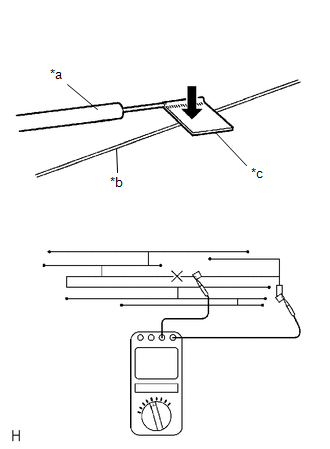
Text in Illustration
|
*a |
Tester Probe |
|
*b |
Antenna Wire |
|
*c |
Aluminum Foil |
| NG |
|
REPAIR GLASS ANTENNA |
|
|
9. |
CHECK AMPLIFIER ANTENNA ASSEMBLY |
(a) Replace the amplifier antenna assembly and check if radio broadcasts can be received normally.
OK:
Radio broadcasts can be received normally.
| OK |
|
END (AMPLIFIER ANTENNA ASSEMBLY WAS DEFECTIVE) |
| NG |
|
|
|
|