| Last Modified: 08-28-2024 | 6.11:8.1.0 | Doc ID: RM100000000VJ1E |
| Model Year Start: 2016 | Model: Sienna | Prod Date Range: [12/2015 - 11/2017] |
| Title: AUDIO / VIDEO: REAR SEAT ENTERTAINMENT SYSTEM: TERMINALS OF ECU; 2016 - 2017 MY Sienna [12/2015 - 11/2017] | ||
TERMINALS OF ECU
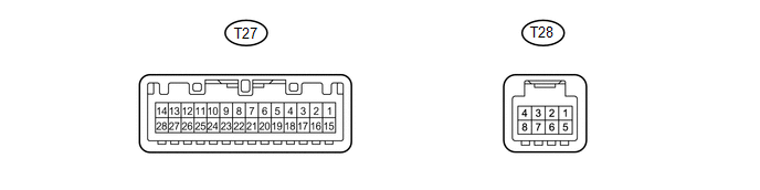
1. TELEVISION DISPLAY ASSEMBLY
|
Terminal No. (Symbol) |
Wiring Color |
Terminal Description |
Condition |
Specified Condition |
|---|---|---|---|---|
|
T27-5 (MUT2) - T27-3 (GND) |
L - BR |
Mute signal |
Disc player assembly is playing → Change modes |
4 V or higher → Below 1 V |
|
T27-21 (TX2-) - T27-3 (GND) |
V - BR |
AVC-LAN communication signal |
Ignition switch ACC |
2 to 3 V |
|
T27-18 (TX1+) - T27-3 (GND) |
B - BR |
AVC-LAN communication signal |
Ignition switch ACC |
2 to 3 V |
|
T27-23 (R1+) - T27-3 (GND) |
B - BR |
Sound signal (Output) |
Ignition switch ACC RSE system is playing |
A waveform synchronized with sound signals is output |
|
T27-24 (R1-) - T27-3 (GND) |
W - BR |
Sound signal (Output) |
Ignition switch ACC RSE system is playing |
A waveform synchronized with sound signals is output |
|
T27-6 (MUT1) - T27-3 (GND) |
R - BR |
Mute signal |
Ignition switch ACC RSE system is playing → Change modes |
4 V or higher → Below 1 V |
|
T27-17 (GND2) - Body ground |
BR - Body ground |
Ground |
Always |
Below 1 V |
|
T27-2 (ACC) - T27-3 (GND) |
GR - BR |
ACC power source |
Ignition switch ACC |
11 to 14 V |
|
T27-15 (+B2) - T27-3 (GND) |
V - BR |
Battery power source |
Always |
11 to 14 V |
|
T27-20 (TX2+) - T27-3 (GND) |
P - BR |
AVC-LAN communication signal |
Ignition switch ACC |
2 to 3 V |
|
T27-19 (TX1-) - T27-3 (GND) |
W - BR |
AVC-LAN communication signal |
Ignition switch ACC |
2 to 3 V |
|
T27-9 (L1+) - T27-3 (GND) |
R - BR |
Sound signal (Output) |
Ignition switch ACC RSE system is playing |
A waveform synchronized with sound signals is output |
|
T27-10 (L1-) - T27-3 (GND) |
G - BR |
Sound signal (Output) |
Ignition switch ACC RSE system is playing |
A waveform synchronized with sound signals is output |
|
T27-11 (SLD1) - T27-3 (GND) |
Shield - BR |
Shield ground |
Always |
Below 1 V |
|
T27-3 (GND) - Body ground |
BR - Body ground |
Ground |
Always |
Below 1 V |
|
T27-1 (+B) - T27-3 (GND) |
V - BR |
Battery power source |
Always |
11 to 14 V |
|
T28-3 (SGN6) - T27-3 (GND) |
Shield - BR |
Shield ground |
Always |
Below 1 V |
|
T28-6 (VD) - T28-7 (VG) |
BR - Y |
Display signal (Input) |
VTR is displayed |
Pulse generation (Refer to waveform 1) |
|
T28-2 (R+) - T27-3 (GND) |
B - BR |
Sound signal (Input) |
External device playing (When video terminal used) |
A waveform synchronized with sound signals is output |
|
T28-4 (L+) - T27-3 (GND) |
R - BR |
Sound signal (Input) |
External device playing (When video terminal used) |
A waveform synchronized with sound signals is output |
|
T27-28 (HP2L) - T27-3 (GND) |
G - BR |
Sound signal (Output) |
Ignition switch ACC RSE system is playing |
A waveform synchronized with sound signals is output |
|
T27-27 (SLD6) - T27-3 (GND) |
Shield - BR |
Shield ground |
Always |
Below 1 V |
|
T27-26 (HP2R) - T27-3 (GND) |
R - BR |
Sound signal (Output) |
Ignition switch ACC RSE system is playing |
A waveform synchronized with sound signals is output |
|
T28-8 (SGN5) - T27-3 (GND) |
Shield - BR |
Shield ground |
Always |
Below 1 V |
|
T28-5 (ADP1) - T27-3 (GND) |
LG - BR |
Ground |
Always |
Below 1 V |
|
T27-14 (HP1L) - T27-3 (GND) |
W - BR |
Sound signal (Output) |
Ignition switch ACC RSE system is playing |
A waveform synchronized with sound signals is output |
|
T27-13 (SLD5) - T27-3 (GND) |
Shield - BR |
Shield ground |
Always |
Below 1 V |
|
T27-12 (HP1R) - T27-3 (GND) |
B - BR |
Sound signal (Output) |
Ignition switch ACC RSE system is playing |
A waveform synchronized with sound signals is output |
(a) Using an oscilloscope, check the waveform.
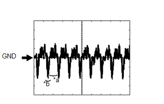
Waveform 1(Reference)
|
Item |
Content |
|---|---|
|
Terminal No. (Symbols) |
T28-6 (VD) - T28-7 (VG) |
|
Tool Setting |
200 mV/DIV., 100 μsec./DIV. |
|
Condition |
External device playing (When video terminal used) |
Text in Illustration
|
*a |
Video Waveform |
|
*b |
Synchronization Signal |
2. DISC PLAYER ASSEMBLY

|
Terminal No. (Symbol) |
Wiring Color |
Terminal Description |
Condition |
Specified Condition |
|---|---|---|---|---|
|
D70-6 (MUTE) - D70-13 (GND) |
L - BR |
Mute signal |
Disc player assembly is playing → Change modes |
4 V or higher → Below 1 V |
|
D70-7 (ACC) - D70-13 (GND) |
GR - BR |
ACC power source |
Ignition switch ACC |
11 to 14 V |
|
D70-8 (+B) - D70-13 (GND) |
V - BR |
Battery power source |
Always |
11 to 14 V |
|
D70-9 (TX+) - D70-13 (GND) |
P - BR |
AVC-LAN communication signal |
Ignition switch ACC |
2 to 3 V |
|
D70-10 (TX-) - D70-13 (GND) |
V - BR |
AVC-LAN communication signal |
Ignition switch ACC |
2 to 3 V |
|
D70-13 (GND) - Body ground |
BR - Body ground |
Ground |
Always |
Below 1 V |
3. HEADPHONE TERMINAL

Text in Illustration
|
*a |
for RH Side |
*b |
for LH Side |
|
Terminal No. (Symbol) |
Wiring Color |
Terminal Description |
Condition |
Specified Condition |
|---|---|---|---|---|
|
S1-1 (HP2R) - Body ground |
R - Body ground |
Sound signal (Input) |
Ignition switch ACC RSE system is playing |
A waveform synchronized with sound signals is output |
|
S1-2 (HP2L) - Body ground |
G - Body ground |
Sound signal (Input) |
Ignition switch ACC RSE system is playing |
A waveform synchronized with sound signals is output |
|
S1-3 (SGN2) - Body ground |
Shield - Body ground |
Shield ground |
Always |
Below 1 V |
|
O1-1 (HP1R) - Body ground |
B - Body ground |
Sound signal (Input) |
Ignition switch ACC RSE system is playing |
A waveform synchronized with sound signals is output |
|
O1-2 (HP1L) - Body ground |
W - Body ground |
Sound signal (Input) |
Ignition switch ACC RSE system is playing |
A waveform synchronized with sound signals is output |
|
O1-3 (SGN1) - Body ground |
Shield - Body ground |
Shield ground |
Always |
Below 1 V |
4. VIDEO TERMINAL

|
Terminal No. (Symbol) |
Wiring Color |
Terminal Description |
Condition |
Specified Condition |
|---|---|---|---|---|
|
P3-1 (VAR+) - Body ground |
B - Body ground |
Sound signal (Output) |
External device playing (When video terminal used) |
A waveform synchronized with sound signals is output |
|
P3-2 (VAL+) - Body ground |
R - Body ground |
Sound signal (Output) |
External device playing (When video terminal used) |
A waveform synchronized with sound signals is output |
|
P3-3 (VA-) - Body ground |
W - Body ground |
Ground |
Always |
Below 1 V |
|
P3-5 (VV+) - P3-6 (VV-) |
BR - Y |
Display signal |
VTR is displayed |
Pulse generation (Refer to waveform 1) |
|
P3-7 (SG) - Body ground |
Shield - Body ground |
Shield ground |
Always |
Below 1 V |
|
P3-8 (ADPG) - Body ground |
LG - Body ground |
Ground |
Always |
Below 1 V |
(a) Using an oscilloscope, check the waveform.
Waveform 1(Reference)
|
Item |
Content |
|---|---|
|
Terminal No. (Symbols) |
P3-5 (VV+) - P3-6 (VV-) |
|
Tool Setting |
200 mV/DIV., 100 μsec./DIV. |
|
Condition |
External device playing (When VTR terminal used) |
Text in Illustration
|
*a |
Video Waveform |
|
*b |
Synchronization Signal |
5. RADIO AND DISPLAY RECEIVER ASSEMBLY (w/o Navigation System) (See page
![2016 - 2017 MY Sienna [12/2015 - 11/2017]; AUDIO / VIDEO: AUDIO AND VISUAL SYSTEM: TERMINALS OF ECU](/t3Portal/stylegraphics/info.gif) )
)
6. NAVIGATION RECEIVER ASSEMBLY (w/ Navigation System) (See page
)
7. STEREO COMPONENT AMPLIFIER ASSEMBLY (w/ Navigation System) (See page
)
|
|
|