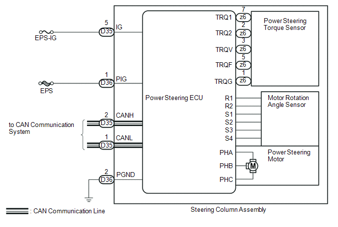
- Steering column assembly
| Last Modified: 08-28-2024 | 6.11:8.1.0 | Doc ID: RM100000000VIZK |
| Model Year Start: 2016 | Model: Sienna | Prod Date Range: [12/2015 - ] |
| Title: POWER ASSIST SYSTEMS: POWER STEERING SYSTEM: C1511-C1514,C1521,C1524,C1528,C1531-C1555; Torque Sensor Circuit Malfunction; 2016 - 2020 MY Sienna [12/2015 - ] | ||
|
DTC |
C1511 |
Torque Sensor Circuit Malfunction |
|
DTC |
C1512 |
Torque Sensor Circuit Malfunction |
|
DTC |
C1513 |
Torque Sensor Circuit Malfunction |
|
DTC |
C1514 |
Torque Sensor Power Supply Abnormal |
|
DTC |
C1521 |
Motor Circuit Malfunction |
|
DTC |
C1524 |
Motor Circuit Malfunction |
|
DTC |
C1528 |
Motor Rotation Angle Sensor Malfunction |
|
DTC |
C1531 |
ECU Malfunction |
|
DTC |
C1532 |
ECU Malfunction |
|
DTC |
C1533 |
ECU Malfunction |
|
DTC |
C1534 |
ECU Malfunction |
|
DTC |
C1555 |
Motor Relay Welding Failure |
DESCRIPTION
The torque sensor converts the rotation torque input to the steering wheel into an electrical signal and sends it to the power steering ECU. Based on this signal, the ECU detects steering effort.
The power steering ECU, power steering torque sensor, power steering motor and motor rotation angle sensor are built into the steering column assembly.
|
DTC No. |
DTC Detection Condition |
Trouble Area |
|---|---|---|
|
C1511 |
Torque sensor (TRQ1) signal error or stop |
|
|
C1512 |
Torque sensor (TRQ2) signal error or stop |
|
|
C1513 |
Deviation between torque sensors TRQ1 and TRQ2 exceeds specified value |
|
|
C1514 |
Torque sensor power source voltage error |
|
|
C1521 |
Short (or open) in motor circuit or abnormal voltage or current in motor circuit |
|
|
C1524 |
Short (or open) in motor circuit or abnormal voltage or current in motor circuit |
|
|
C1528 |
Motor rotation angle sensor malfunction |
|
|
C1531 |
ECU internal malfunction (CPU malfunction) |
|
|
C1532 |
ECU internal malfunction (Peripheral circuit malfunction) |
|
|
C1533 |
ECU internal malfunction (Substrate temperature sensor malfunction) |
|
|
C1534 |
ECU internal malfunction (EEPROM error) |
|
|
C1555 |
Motor relay circuit malfunction |
WIRING DIAGRAM

CAUTION / NOTICE / HINT
NOTICE:
PROCEDURE
|
1. |
CHECK CONNECTOR CONNECTION CONDITION (STEERING COLUMN ASSEMBLY) |
(a) Check the installation condition of the torque sensor, power steering motor and rotation sensor connectors.
OK:
Torque sensor, power steering motor and rotation angle sensor connectors are securely connected to the power steering ECU.
| OK |

|
| NG |

|
CONNECT CONNECTOR |
|
|
|
![2016 - 2020 MY Sienna [12/2015 - ]; POWER ASSIST SYSTEMS: POWER STEERING SYSTEM: REGISTRATION](/t3Portal/stylegraphics/info.gif)