- Stop light switch
- Brake pedal load sensing switch
- Master cylinder pressure sensor
| Last Modified: 08-28-2024 | 6.11:8.1.0 | Doc ID: RM100000000VIWK |
| Model Year Start: 2016 | Model: Sienna | Prod Date Range: [12/2015 - 11/2017] |
| Title: BRAKE CONTROL / DYNAMIC CONTROL SYSTEMS: VEHICLE STABILITY CONTROL SYSTEM: C1281; Master Cylinder Pressure Sensor Output Malfunction (Test Mode DTC); 2016 - 2017 MY Sienna [12/2015 - 11/2017] | ||
|
DTC |
C1281 |
Master Cylinder Pressure Sensor Output Malfunction (Test Mode DTC) |
DESCRIPTION
DTC C1281 will be cleared when the master cylinder pressure sensor sends a master cylinder pressure signal or when Test Mode ends. DTC C1281 is output only in Test Mode.
|
DTC Code |
DTC Detection Condition |
Trouble Area |
|---|---|---|
|
C1281 |
Detected only during Test Mode. |
|
WIRING DIAGRAM
Refer to DTCs C1425 and C1429 (See page
![2016 - 2017 MY Sienna [12/2015 - 11/2017]; BRAKE CONTROL / DYNAMIC CONTROL SYSTEMS: VEHICLE STABILITY CONTROL SYSTEM: C1425; Open in Stop Light Switch Circuit+](/t3Portal/stylegraphics/info.gif) , or
).
, or
).
CAUTION / NOTICE / HINT
NOTICE:
When replacing the brake actuator assembly, perform zero point calibration and store system information (See page
).
PROCEDURE
|
1. |
CHECK STOP LIGHT OPERATION |
(a) Check that the stop lights come on when the brake pedal is depressed, and go off when the brake pedal is released.
OK
|
Condition |
Illumination Condition |
|---|---|
|
Brake pedal depressed |
ON |
|
Brake pedal released |
OFF |
| NG |

|
INSPECT STOP LIGHT CIRCUIT (See page
|
|

|
2. |
READ VALUE USING TECHSTREAM (STOP LIGHT SWITCH AND BRAKE PEDAL LOAD SENSING SWITCH) |
(a) Connect the Techstream to the DLC3.
(b) Turn the ignition switch to ON.
(c) Turn the Techstream on.
(d) Enter the following menus: Chassis / ABS/VSC/ TRAC / Data List.
(e) Select the Data List on the Techstream (See page
).
ABS/VSC/TRAC
|
Tester Display |
Measurement Item/Range |
Normal Condition |
Diagnostic Note |
|---|---|---|---|
|
Stop Light SW |
Stop light switch / ON or OFF |
ON: Brake pedal depressed OFF: Brake pedal released |
- |
|
Brake Pedal Load Sensing SW |
Brake pedal load sensing switch / ON or OFF |
ON: Brake pedal depressed beyond the specified point OFF: Brake pedal not depressed beyond the specified point |
- |
(f) Check that the stop light switch display and brake pedal load sensing switch display observed on the Techstream change according to brake pedal operation.
OK:
The Techstream displays ON or OFF according to brake pedal operation.
(g) Slowly depress the brake pedal, and check when the stop light switch and brake pedal load sensing switch turn ON.
OK:
First the stop light switch should turn ON, and then the brake pedal load sensing switch should turn ON.
Result
|
Result |
Proceed to |
|---|---|
|
OK |
A |
|
Turning on of the stop light switch is not confirmed |
B |
|
Turning on of the brake pedal load sensing switch is not confirmed |
C |
|
The brake pedal load sensing switch turns on first |
D |
| B |
|
| C |
|
| D |
|
|
|
3. |
READ VALUE USING TECHSTREAM (MASTER CYLINDER PRESSURE SENSOR) |
(a) Enter the following menus: Chassis / ABS/VSC/ TRAC / Data List.
(b) Select the Data List on the Techstream (See page
).
ABS/VSC/TRAC
|
Tester Display |
Measurement Item/Range |
Normal Condition |
Diagnostic Note |
|---|---|---|---|
|
Master Cylinder Sensor |
Master cylinder pressure sensor / min.: 0 V, max.: 5 V |
When brake pedal is released: 0.3 to 0.9 V |
Reading increases when brake pedal is depressed |
(c) Check that the brake fluid pressure value of the master cylinder pressure sensor observed on the Techstream changes when the brake pedal is depressed.
OK:
When the pedal is depressed, voltage displayed on the Techstream increases.
| NG |
|
|
|
4. |
PERFORM TEST MODE (SIGNAL CHECK) |
(a) Turn the ignition switch off.
(b) Perform the sensor check in the Test Mode procedure (See page
).
OK:
All Test Mode DTCs are cleared.
| OK |
|
CHECK FOR INTERMITTENT PROBLEMS (See page
|
| NG |
|
|
5. |
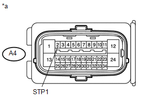
INSPECT SKID CONTROL ECU (STP1 TERMINAL) |
|
(a) Turn the ignition switch off. |
|
(b) Make sure that there is no looseness at the locking part and the connecting part of the connector.
(c) Disconnect the skid control ECU connector.
(d) Measure the voltage according to the value(s) in the table below.
Standard Voltage:
|
Tester Connection |
Switch Condition |
Specified Condition |
|---|---|---|
|
A4-2 (STP1) - Body ground |
Stop light switch ON (Brake pedal depressed) |
8 to 14 V |
|
A4-2 (STP1) - Body ground |
Stop light switch OFF (Brake pedal released) |
Below 1.5 V |
Text in Illustration
|
*a |
Front view of wire harness connector (to Skid Control ECU) |
| OK |
|
| NG |
|
REPAIR OR REPLACE HARNESS OR CONNECTOR (STP1 CIRCUIT) |
|
6. |
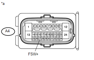
INSPECT SKID CONTROL ECU (FSW+ TERMINAL) |
|
(a) Turn the ignition switch off. |
|
(b) Make sure that there is no looseness at the locking part and the connecting part of the connector.
(c) Disconnect the skid control ECU connector.
(d) Measure the resistance according to the value(s) in the table below.
Standard Resistance:
|
Tester Connection |
Switch Condition |
Specified Condition |
|---|---|---|
|
A4-27 (FSW+) - Body ground |
Brake pedal load sensing switch OFF (Brake pedal depressed) |
0.9 to 1.1 kΩ |
|
A4-27 (FSW+) - Body ground |
Brake pedal load sensing switch ON (Brake pedal released) |
192 to 234 Ω |
Text in Illustration
|
*a |
Front view of wire harness connector (to Skid Control ECU) |
| OK |
|
| NG |
|
REPAIR OR REPLACE HARNESS OR CONNECTOR (FSW+ CIRCUIT) |
|
7. |
CHECK BRAKE PEDAL AND STOP LIGHT SWITCH INSTALLATION |
(a) Turn the ignition switch off.
(b) Check the brake pedal height and stop light switch installation (See page
).
OK:
The brake pedal height and stop light switch installation are normal.
| OK |
|
REPLACE BRAKE PEDAL SUB-ASSEMBLY (BRAKE PEDAL LOAD SENSING SWITCH) |
| NG |
|
|
|
|