- Yaw rate and acceleration sensor power source circuit
- Sensor installation
- Yaw rate and acceleration sensor (w/ VDIM)
- Yaw rate and acceleration sensor (airbag sensor assembly) (w/o VDIM)
- Skid control ECU (brake actuator assembly)
| Last Modified: 08-28-2024 | 6.11:8.1.0 | Doc ID: RM100000000VIWJ |
| Model Year Start: 2016 | Model: Sienna | Prod Date Range: [12/2015 - 11/2017] |
| Title: BRAKE CONTROL / DYNAMIC CONTROL SYSTEMS: VEHICLE STABILITY CONTROL SYSTEM: C1279; Acceleration Sensor Output Voltage Malfunction (Test Mode DTC); 2016 - 2017 MY Sienna [12/2015 - 11/2017] | ||
|
DTC |
C1279 |
Acceleration Sensor Output Voltage Malfunction (Test Mode DTC) |
DESCRIPTION
DTC C1279 can be cleared when the yaw rate and acceleration sensor sends a yaw rate and/or acceleration signal or when Test Mode ends. DTC C1279 is output only in Test Mode.
|
DTC Code |
DTC Detection Condition |
Trouble Area |
|---|---|---|
|
C1279 |
Detected only during Test Mode. |
|
WIRING DIAGRAM
Refer to DTCs C1232, C1243 and C1245 (See page
![2016 - 2017 MY Sienna [12/2015 - 11/2017]; BRAKE CONTROL / DYNAMIC CONTROL SYSTEMS: VEHICLE STABILITY CONTROL SYSTEM: C1232,C1243,C1245; Acceleration Sensor Stuck Malfunction+](/t3Portal/stylegraphics/info.gif) ).
).
CAUTION / NOTICE / HINT
NOTICE:
When replacing the brake actuator assembly or yaw rate and acceleration sensor, perform zero point calibration and store system information (See page
).
PROCEDURE
|
1. |
CHECK VEHICLE EQUIPMENT |
(a) Confirm whether the vehicle is w/ VDIM or w/o VDIM.
Result
|
Result |
Proceed to |
|---|---|
|
w/ VDIM |
A |
|
w/o VDIM |
B |
| B |

|
|

|
2. |
CHECK YAW RATE AND ACCELERATION SENSOR INSTALLATION |
(a) Check that the yaw rate and acceleration sensor has been installed properly (See page
).
OK:
The sensor is tightened to the specified torque.
The sensor is not installed in a tilted position.
| NG |
|
|
|
3. |
CHECK HARNESS AND CONNECTOR (IG TERMINAL) |
|
(a) Make sure that there is no looseness at the locking part and the connecting part of the connectors. |
|
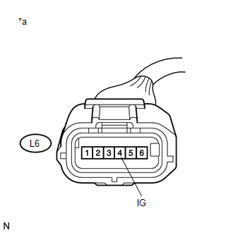
(b) Disconnect the yaw rate and acceleration sensor connector.
(c) Turn the ignition switch to ON.
(d) Measure the voltage according to the value(s) in the table below.
Standard Voltage:
|
Tester Connection |
Switch Condition |
Specified Condition |
|---|---|---|
|
L6-4 (IG) - Body ground |
Ignition switch ON |
11 to 14 V |
Text in Illustration
|
*a |
Front view of wire harness connector (to Yaw Rate and Acceleration Sensor) |
| NG |
|
REPAIR OR REPLACE HARNESS OR CONNECTOR (IG CIRCUIT) |
|
|
4. |
CHECK HARNESS AND CONNECTOR (GND TERMINAL) |
|
(a) Turn the ignition switch off. |
|
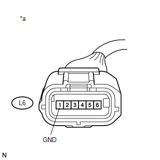
(b) Measure the resistance according to the value(s) in the table below.
Standard Resistance:
|
Tester Connection |
Condition |
Specified Condition |
|---|---|---|
|
L6-1 (GND) - Body ground |
Always |
Below 1 Ω |
Text in Illustration
|
*a |
Front view of wire harness connector (to Yaw Rate and Acceleration Sensor) |
| OK |
|
| NG |
|
REPAIR OR REPLACE HARNESS OR CONNECTOR (GND CIRCUIT) |
|
5. |
CHECK AIRBAG SENSOR ASSEMBLY INSTALLATION |
(a) Check that the yaw rate and acceleration sensor (airbag sensor assembly) has been installed properly (See page
).
OK:
The sensor is tightened to the specified torque.
The sensor is not installed in a tilted position.
| NG |
|
|
|
6. |
CHECK HARNESS AND CONNECTOR (IG2 TERMINAL) |
(a) Make sure that there is no looseness at the locking part and the connecting part of the connectors.
(b) Disconnect the yaw rate and acceleration sensor (airbag sensor assembly) connector.
(c) Turn the ignition switch to ON.
|
(d) Measure the voltage according to the value(s) in the table below. Standard Voltage:
Text in Illustration
|
|
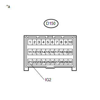
| NG |
|
REPAIR OR REPLACE HARNESS OR CONNECTOR (IG2 CIRCUIT) |
|
|
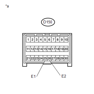
7. |
CHECK HARNESS AND CONNECTOR (E1 AND E2 TERMINAL) |
(a) Turn the ignition switch off.
|
(b) Measure the resistance according to the value(s) in the table below. Standard Resistance:
Text in Illustration
|
|
| OK |
|
| NG |
|
REPAIR OR REPLACE HARNESS OR CONNECTOR (E1 AND E2 CIRCUIT) |
|
|
|