- STOP fuse
- Stop light switch assembly
- Stop light switch circuit
- Skid control ECU (brake actuator assembly)
| Last Modified: 08-28-2024 | 6.11:8.1.0 | Doc ID: RM100000000VIWC |
| Model Year Start: 2016 | Model: Sienna | Prod Date Range: [12/2015 - 11/2017] |
| Title: BRAKE CONTROL / DYNAMIC CONTROL SYSTEMS: VEHICLE STABILITY CONTROL SYSTEM: C1425; Open in Stop Light Switch Circuit; 2016 - 2017 MY Sienna [12/2015 - 11/2017] | ||
|
DTC |
C1425 |
Open in Stop Light Switch Circuit |
DESCRIPTION
The skid control ECU (housed in the actuator assembly) inputs stop light switch signals and the condition of brake operation.
The skid control ECU has an open detection circuit, which outputs this DTC when detecting an open in the stop light input line or the ground line of the stop light circuit with the stop light switch off (brake pedal not depressed).
|
DTC Code |
DTC Detection Condition |
Trouble Area |
|---|---|---|
|
C1425 |
When IG1 terminal voltage is between 9.5 and 17.4 V, an open stop light switch circuit continues for 3 seconds or more. |
|
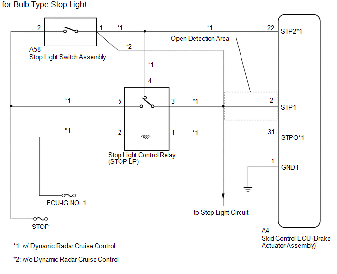
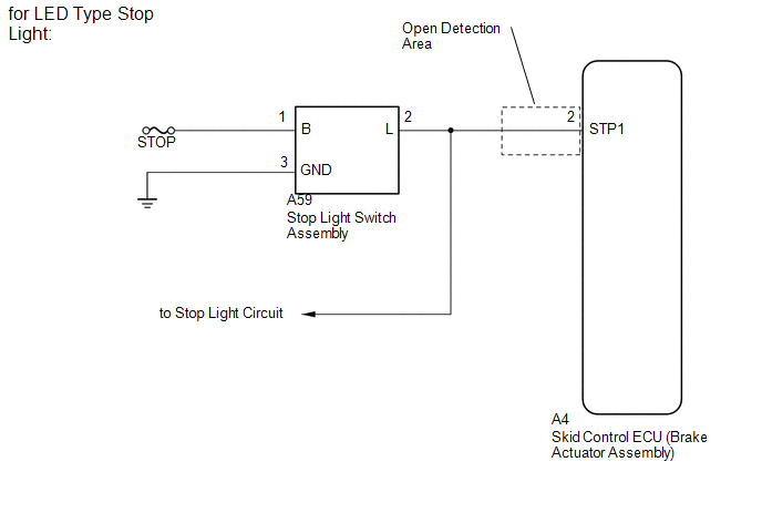
WIRING DIAGRAM
CAUTION / NOTICE / HINT
NOTICE:
-
When replacing the brake actuator assembly, perform zero point calibration and store system information (See page
![2016 - 2017 MY Sienna [12/2015 - 11/2017]; BRAKE CONTROL / DYNAMIC CONTROL SYSTEMS: VEHICLE STABILITY CONTROL SYSTEM: CALIBRATION](/t3Portal/stylegraphics/info.gif) ).
).
- Inspect the fuses for circuits related to this system before performing the following inspection procedure.
PROCEDURE
|
1. |
CHECK STOP LIGHT OPERATION |
(a) Check that the stop lights come on when the brake pedal is depressed, and go off when the brake pedal is released.
OK
|
Condition |
Illumination Condition |
|---|---|
|
Brake pedal depressed |
ON |
|
Brake pedal released |
OFF |
| NG |

|
|

|
2. |
READ VALUE USING TECHSTREAM (STOP LIGHT SW) |
(a) Connect the Techstream to the DLC3.
(b) Turn the ignition switch to ON.
(c) Turn the Techstream on.
(d) Enter the following menus: Chassis / ABS/VSC/ TRAC / Data List.
(e) According to the display on the Techstream, read the Data List.
ABS/VSC/TRAC
|
Tester Display |
Measurement Item/Range |
Normal Condition |
Diagnostic Note |
|---|---|---|---|
|
Stop Light SW |
Stop light switch assembly / ON or OFF |
ON: Brake pedal depressed OFF: Brake pedal released |
- |
(f) Check that the stop light switch display observed on the Techstream changes according to brake pedal operation.
OK:
The Techstream displays ON or OFF according to brake pedal operation.
| NG |
|
|
|
3. |
RECONFIRM DTC |
(a) Turn the ignition switch off.
(b) Clear the DTCs (See page
).
(c) Start the engine.
(d) Depress the brake pedal several times to test the stop light circuit.
(e) Check if the same DTC is recorded (See page
).
Result
|
Result |
Proceed to |
|---|---|
|
DTC (C1425) is not output |
A |
|
DTC (C1425) is output |
B |
HINT:
If troubleshooting has been carried out according to Problem Symptoms Table, refer back to the table and proceed to the next step (See page
).
| A |
|
USE SIMULATION METHOD TO CHECK (See page
|
| B |
|
|
4. |
INSPECT STOP LIGHT SWITCH ASSEMBLY |
(a) for Bulb Type Stop Light
|
(1) Measure the resistance according to the value(s) in the table below. Standard Resistance:
Text in Illustration
|
|
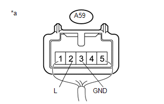
(b) for LED Type Stop Light
(1) Reconnect the stop light switch assembly connector.
|
(2) Measure the resistance according to the value(s) in the table below. Standard Voltage:
Text in Illustration
Result
|
|
| B |
|
| C |
|
|
|
5. |
CHECK HARNESS AND CONNECTOR (SWITCH INPUT TERMINAL) |
(a) Turn the ignition switch off.
(b) Remove the stop light control relay (STOP LP relay).
|
(c) Measure the voltage according to the value(s) in the table below. Standard Voltage:
Text in Illustration
|
|
| NG |
|
REPAIR OR REPLACE HARNESS OR CONNECTOR (SWITCH INPUT CIRCUIT) |
|
|
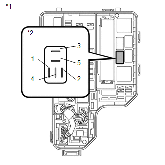
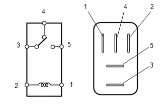
6. |
INSPECT STOP LIGHT CONTROL RELAY |
|
(a) Measure the resistance according to the value(s) in the table below. Standard Resistance:
Text in Illustration
|
|
| NG |
|
REPLACE STOP LIGHT CONTROL RELAY |
|
|
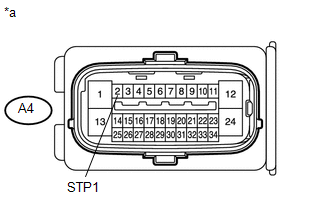
7. |
CHECK HARNESS AND CONNECTOR (STP1 TERMINAL) |
(a) Turn the ignition switch off.
(b) Make sure that there is no looseness at the locking part and the connecting part of the connector.
(c) Disconnect the A4 skid control ECU (brake actuator assembly) connector.
|
(d) Measure the voltage according to the value(s) in the table below. Standard Voltage:
Text in Illustration
HINT: If troubleshooting has been carried out according to Problem Symptoms Table, refer back to the table and proceed to the next step before replacing parts (See page
|
|
| NG |
|
REPAIR OR REPLACE HARNESS OR CONNECTOR (STP1 CIRCUIT) |
|
|
8. |
RECONFIRM DTC |
(a) Turn the ignition switch off.
(b) Reconnect the A4 skid control ECU (brake actuator assembly) connector.
(c) Clear the DTCs (See page
).
(d) Turn the ignition switch off.
(e) Start the engine.
(f) Depress the brake pedal several times to test the stop light circuit.
(g) Check if the same DTC is output (See page
).
Result
|
Result |
Proceed to |
|---|---|
|
DTC C1425 is not output. |
A |
|
DTC C1425 is output. |
B |
HINT:
- If the lighting system is normal but the DTC is still output, replace the skid control ECU (brake actuator assembly).
-
If troubleshooting has been carried out according to Problem Symptoms Table, refer back to the table and proceed to the next step (See page
).
| A |
|
USE SIMULATION METHOD TO CHECK (See page
|
| B |
|
INSPECT LIGHTING SYSTEM (STOP LIGHT CIRCUIT) (See page
|
|
9. |
CHECK HARNESS AND CONNECTOR (STP1 TERMINAL) |
(a) Turn the ignition switch off.
(b) Make sure that there is no looseness at the locking part and the connecting part of the connector.
(c) Disconnect the skid control ECU (brake actuator assembly) connector.
|
(d) Measure the voltage according to the value(s) in the table below. Standard Voltage:
Text in Illustration
HINT: If troubleshooting has been carried out according to Problem Symptoms Table, refer back to the table and proceed to the next step before replacing parts (See page
|
|
| OK |
|
| NG |
|
REPAIR OR REPLACE HARNESS OR CONNECTOR (STP1 CIRCUIT) |
|
|
|