- An open in the sensor signal circuit of a malfunctioning area occurs 255 times or more.
- At a vehicle speed 20 km/h (12 mph) or more, noise occurs in the sensor signals of a malfunctioning wheel 75 times or more within 5 seconds.
- At a vehicle speed 10 km/h (6 mph) or more, noise occurs once per rotor rotation for 15 seconds or more.
| Last Modified: 08-28-2024 | 6.11:8.1.0 | Doc ID: RM100000000VIVU |
| Model Year Start: 2016 | Model: Sienna | Prod Date Range: [12/2015 - 11/2017] |
| Title: BRAKE CONTROL / DYNAMIC CONTROL SYSTEMS: VEHICLE STABILITY CONTROL SYSTEM: C1415,C1416; Rear Speed Sensor RH Output Malfunction; 2016 - 2017 MY Sienna [12/2015 - 11/2017] | ||
|
DTC |
C1415 |
Rear Speed Sensor RH Output Malfunction |
|
DTC |
C1416 |
Rear Speed Sensor LH Output Malfunction |
DESCRIPTION
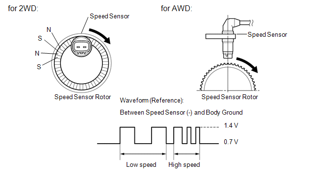
The speed sensor detects wheel speed and sends the appropriate signals to the skid control ECU. These signals are used for ABS control.
- Speed sensor rotors have rows of alternating N and S magnetic poles and their magnetic fields change when the rotors turn. Each speed sensor detects that magnetic change and sends a pulse signal to the skid control ECU (for 2WD).
- Speed sensor rotors have 48 serrations and their magnetic fields change when the rotors turn. Each speed sensor detects that magnetic change and sends a pulse signal to the skid control ECU (for AWD).
The hall IC type speed sensor uses the frequency of output pulses to detect the vehicle speed. Because the sensor outputs digital pulses, it can detect vehicle speeds even when the vehicle is nearly stationary.
HINT:
Measure the connection status between the sensor connector and the vehicle wire harness.
|
DTC Code |
DTC Detection Condition |
Trouble Area |
|---|---|---|
|
C1415 C1416 |
Any of the following is detected: |
|
HINT:
- DTC C1415 is for the rear speed sensor RH.
- DTC C1416 is for the rear speed sensor LH.
WIRING DIAGRAM
Refer to DTCs C1403 and C1404 (See page
![2016 - 2017 MY Sienna [12/2015 - 11/2017]; BRAKE CONTROL / DYNAMIC CONTROL SYSTEMS: VEHICLE STABILITY CONTROL SYSTEM: C1403,C1404; Rear Speed Sensor RH Malfunction+](/t3Portal/stylegraphics/info.gif) ).
).
CAUTION / NOTICE / HINT
NOTICE:
When replacing the brake actuator assembly, perform zero point calibration and store system information (See page
).
PROCEDURE
|
1. |
CHECK HARNESS AND CONNECTOR (MOMENTARY INTERRUPTION) |
(a) Using the Techstream, check for any momentary interruption in the wire harness and connector corresponding to the DTC (See page
).
ABS/VSC/TRAC
|
Tester Display |
Measurement Item/Range |
Normal Condition |
Diagnostic Note |
|---|---|---|---|
|
RR Speed Open |
RR speed sensor open detection / Error or Normal |
Error: Momentary interruption Normal: Normal |
- |
|
RL Speed Open |
RL speed sensor open detection / Error or Normal |
Error: Momentary interruption Normal: Normal |
- |
OK:
There are no momentary interruptions.
HINT:
Perform the above inspection before removing the sensor and connector.
| NG |

|
|

|
2. |
READ VALUE USING TECHSTREAM (REAR SPEED SENSOR) |
(a) Turn the ignition switch off.
(b) Connect the Techstream to the DLC3.
(c) Start the engine.
(d) Turn the Techstream on.
(e) Enter the following menus: Chassis / ABS/VSC/ TRAC / Data List.
(f) Select the Data List on the Techstream (See page
).
ABS/VSC/TRAC
|
Tester Display |
Measurement Item/Range |
Normal Condition |
Diagnostic Note |
|---|---|---|---|
|
RR Wheel Speed |
Rear wheel speed sensor RH reading / Min.: 0 km/h (0 mph), Max.: 326 km/h (202 mph) |
Vehicle stopped: 0 km/h (0 mph) |
When driving at constant speed: No large fluctuations |
|
RL Wheel Speed |
Rear wheel speed sensor LH reading / Min.: 0 km/h (0 mph), Max.: 326 km/h (202 mph) |
Vehicle stopped: 0 km/h (0 mph) |
When driving at constant speed: No large fluctuations |
(g) Check that the speed value output from the speed sensor displayed on the Techstream.
HINT:
Factors that affect the indicated vehicle speed include tire size, tire inflation, and tire wear. The speed indicated on the speedometer has an allowable margin of error. This can be tested using a speedometer tester (calibrated chassis dynamometer). For details about testing and the margin of error, see the reference chart (See page
).
OK:
The speed value output from the speed sensor displayed on the Techstream is the similar speed as indicated on the speedometer.
| NG |
|
|
|
3. |
RECONFIRM DTC |
(a) Turn the ignition switch off.
(b) Clear the DTCs (See page
).
(c) Start the engine.
(d) Drive the vehicle at a speed of 40 km/h (25 mph) or more for at least 60 seconds.
(e) Check if the same DTC is recorded (See page
).
Result
|
Result |
Proceed to |
|---|---|
|
DTCs (C1415 and C1416) are not output |
A |
|
DTCs (C1415 and/or C1416) are output |
B |
HINT:
If troubleshooting has been carried out according to Problem Symptoms Table, refer back to the table and proceed to the next step (See page
).
| A |
|
CHECK FOR INTERMITTENT PROBLEMS (See page
|
| B |
|
|
4. |
CHECK REAR SPEED SENSOR INSTALLATION |
|
(a) Turn the ignition switch off. |
|
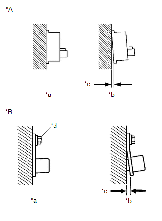
(b) Check the speed sensor installation (for 2WD).
OK:
There is no clearance between the sensor and the rear axle carrier.
(c) Check the speed sensor installation (for AWD).
OK:
There is no clearance between the sensor and the rear axle carrier.
The installation bolt is tightened properly.
Torque
8.0 N*m (82 kgf*cm, 71 in.*lbf)
Text in Illustration
|
*A |
for 2WD |
|
*B |
for AWD |
|
*a |
OK |
|
*b |
NG |
|
*c |
Clearance |
|
*d |
8.0 N*m (82 kgf*cm, 71 in.*lbf) |
Result
|
Result |
Proceed to |
|---|---|
|
OK (for AWD) |
A |
|
OK (for 2WD) |
B |
|
NG (for AWD) |
C |
|
NG (for 2WD) |
D |
| B |
|
| C |
|
| D |
|
|
|
5. |
CHECK REAR SPEED SENSOR TIP |
(a) Remove the rear speed sensor (See page
).
(b) Check the speed sensor tip.
OK:
No scratches, oil, or foreign matter on the sensor tip.
HINT:
- If the sensor is contaminated with oil or other foreign material, clean the sensor.
- If there is iron powder sticking to the rotor, this will result in a malfunction, so confirm that the rotor is not contaminated with foreign material before replacing the sensor.
NOTICE:
Check the speed sensor signal after cleaning or replacement (See page
).
| NG |
|
CLEAN OR REPLACE REAR SPEED SENSOR |
|
|
6. |
CHECK REAR SPEED SENSOR ROTOR |
(a) Remove the rear speed sensor rotor (See page
).
(b) Check the speed sensor rotor.
OK:
No scratches, oil, or foreign matter on the rotor.
Result
|
Result |
Proceed to |
|---|---|
|
NG |
A |
|
OK |
B |
NOTICE:
Check the speed sensor signal after cleaning or replacement (See page
).
HINT:
If the front speed sensor rotor needs to be replaced, replace it together with the rear drive outboard joint shaft assembly.
| A |
|
CLEAN OR REPLACE REAR SPEED SENSOR ROTOR |
|
|
7. |
CHECK HARNESS AND CONNECTOR (SKID CONTROL ECU - REAR SPEED SENSOR) |
(a) for 2WD
(1) Make sure that there is no looseness at the locking part and the connecting part of the connector.
(2) Disconnect the skid control ECU connector.
(3) Measure the resistance according to the value(s) in the table below.
Standard Resistance:
for RH
|
Tester Connection |
Condition |
Specified Condition |
|---|---|---|
|
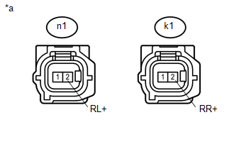
A4-17 (RR+) - k1-2 (RR+) |
Always |
Below 1 Ω |
|
A4-17 (RR+) - Body ground |
Always |
10 kΩ or higher |
|
A4-16 (RR-) - k1-1 (RR-) |
Always |
Below 1 Ω |
|
A4-16 (RR-) - Body ground |
Always |
10 kΩ or higher |
for LH
|
Tester Connection |
Condition |
Specified Condition |
|---|---|---|
|
A4-5 (RL+) - n1-2 (RL+) |
Always |
Below 1 Ω |
|
A4-5 (RL+) - Body ground |
Always |
10 kΩ or higher |
|
A4-4 (RL-) - n1-1 (RL-) |
Always |
Below 1 Ω |
|
A4-4 (RL-) - Body ground |
Always |
10 kΩ or higher |
(b) for AWD
(1) Make sure that there is no looseness at the locking part and the connecting part of the connector.
(2) Disconnect the skid control ECU connector.
(3) Measure the resistance according to the value(s) in the table below.
Standard Resistance:
for RH
|
Tester Connection |
Condition |
Specified Condition |
|---|---|---|
|
A4-17 (RR+) - L41-1 (RR+) |
Always |
Below 1 Ω |
|
A4-17 (RR+) - Body ground |
Always |
10 kΩ or higher |
|
A4-16 (RR-) - L41-2 (RR-) |
Always |
Below 1 Ω |
|
A4-16 (RR-) - Body ground |
Always |
10 kΩ or higher |
for LH
|
Tester Connection |
Condition |
Specified Condition |
|---|---|---|
|
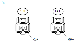
A4-5 (RL+) - K30-1 (RL+) |
Always |
Below 1 Ω |
|
A4-5 (RL+) - Body ground |
Always |
10 kΩ or higher |
|
A4-4 (RL-) - K30-2 (RL-) |
Always |
Below 1 Ω |
|
A4-4 (RL-) - Body ground |
Always |
10 kΩ or higher |
| NG |
|
REPAIR OR REPLACE HARNESS OR CONNECTOR |
|
|
8. |
INSPECT SKID CONTROL ECU (SENSOR INPUT) |
(a) for 2WD
|
(1) Reconnect the skid control ECU connector. |
|
(2) Turn the ignition switch to ON.
(3) Measure the voltage according to the value(s) in the table below.
Standard Voltage:
for RH
|
Tester Connection |
Switch Condition |
Specified Condition |
|---|---|---|
|
k1-2 (RR+) - Body ground |
Ignition switch ON |
8 to 14 V |
for LH
|
Tester Connection |
Switch Condition |
Specified Condition |
|---|---|---|
|
n1-2 (RL+) - Body ground |
Ignition switch ON |
8 to 14 V |
Text in Illustration
|
*a |
Front view of wire harness connector (to Rear Speed Sensor) |
(b) for AWD
|
(1) Reconnect the skid control ECU connector. |
|
(2) Turn the ignition switch to ON.
(3) Measure the voltage according to the value(s) in the table below.
Standard Voltage:
for RH
|
Tester Connection |
Switch Condition |
Specified Condition |
|---|---|---|
|
L41-1 (RR+) - Body ground |
Ignition switch ON |
8 to 14 V |
for LH
|
Tester Connection |
Switch Condition |
Specified Condition |
|---|---|---|
|
K30-1 (RL+) - Body ground |
Ignition switch ON |
8 to 14 V |
Text in Illustration
|
*a |
Front view of wire harness connector (to Rear Speed Sensor) |
Result
|
Result |
Proceed to |
|---|---|
|
OK (for 2WD) |
A |
|
OK (for AWD) |
B |
|
NG |
C |
NOTICE:
Check the speed sensor signal after replacement (See page
).
HINT:
If troubleshooting has been carried out according to Problem Symptoms Table, refer back to the table and proceed to the next step (See page
).
| A |
|
| B |
|
| C |
|
|
|
|