![2016 - 2017 MY Sienna [12/2015 - 11/2017]; BRAKE CONTROL / DYNAMIC CONTROL SYSTEMS: VEHICLE STABILITY CONTROL SYSTEM: TS and CG Terminal Circuit](/t3Portal/stylegraphics/info.gif)
- ECM
- CAN communication system (Skid control ECU to ECM)
- Skid control ECU (brake actuator assembly)
| Last Modified: 08-28-2024 | 6.11:8.1.0 | Doc ID: RM100000000VIVH |
| Model Year Start: 2016 | Model: Sienna | Prod Date Range: [12/2015 - 11/2017] |
| Title: BRAKE CONTROL / DYNAMIC CONTROL SYSTEMS: VEHICLE STABILITY CONTROL SYSTEM: TEST MODE PROCEDURE; 2016 - 2017 MY Sienna [12/2015 - 11/2017] | ||
TEST MODE PROCEDURE
1. SENSOR CHECK USING TEST MODE (SIGNAL CHECK) (When Using the Techstream)
NOTICE:
After replacement of the brake actuator assembly and/or yaw rate and acceleration sensor, perform zero point calibration of the yaw rate and acceleration sensor.
HINT:
- If the ignition switch is turned from ON to ACC or off during Test Mode (signal check), DTCs recorded during the sensor check will be cleared.
- During Test Mode (signal check), the skid control ECU (brake actuator assembly) records all DTCs detected in the sensor check. By performing Test Mode (signal check), the codes are cleared if a normal condition is confirmed. The remaining codes are the codes where a malfunction was found.
(a) Procedure to enter Test Mode
(1) Turn the ignition switch off.
(2) Check that the steering wheel is centered.
(3) Check that the shift lever is in P.
(4) Connect the Techstream to the DLC3.
(5) Turn the ignition switch to ON.
(6) Turn the Techstream on.
(7) Switch the skid control ECU (brake actuator assembly) to Test Mode using the Techstream. Enter the following menus: Chassis / ABS/VSC/TRAC / Utility / Signal Check.
(8) Check that the ABS warning and SLIP indicator lights come on for several seconds and then blink in Test Mode.
HINT:
If the ABS warning and SLIP indicator lights do not blink, inspect the TS and CG terminal circuit and ABS warning and SLIP indicator light circuits.
|
Trouble Area |
See Procedure |
|---|---|
|
TS and CG terminal circuit |
|
|
ABS warning light circuit (Remains on) |
|
|
ABS warning light circuit (Does not come on) |
|
|
SLIP indicator light circuit (Remains on) |
|
|
SLIP indicator light circuit (Does not come on) |
|
(9) Check the ABS sensors.
HINT:
Check that the ABS warning light is blinking in the Test Mode blinking pattern before performing the ABS sensor check.
(b) Acceleration Sensor Check
(1) Keep the vehicle stationary on a level surface for 1 second or more.
HINT:
The acceleration sensor check can be performed with the master cylinder pressure sensor check below.
(c) Lost Booster Pressure Judgement Check and Master Cylinder Pressure Sensor Zero Point Calibration
NOTICE:
Perform a check in the lost booster pressure state (vacuum in the booster is depressurized).
(1) Turn the ignition switch to ON.
(2) Check that the brake warning light comes on when depressing the brake pedal with a force greater than 59 N (6 kgf, 13.2 lbf) for 1 second or more. (The lost booster pressure state is judged as normal.)
(3) Start the engine while depressing the brake pedal with a force greater than 59 N (6 kgf, 13.2 lbf) for 1 second or more.
(4) Check that the brake warning light goes off when quickly releasing the brake pedal. (The lost booster pressure state is judged as normal.)
(5) Leave the vehicle for 1 second or more. (Master cylinder pressure sensor zero point calibration)
NOTICE:
- If depressing the brake pedal slowly or repeatedly, the master cylinder pressure sensor zero point calibration is not performed normally.
- If the lost booster pressure judgement check results are not normal, then the master cylinder pressure sensor check cannot be performed.
- If rechecking after the engine has started, end Test Mode, enter Test Mode again, and release vacuum in the booster by pumping the brake pedal prior to rechecking.
(d) Master Cylinder Pressure Sensor Check
(1) Leave the vehicle in a stationary condition and release the brake pedal for 1 second or more, then quickly and continuously depress the brake pedal with a force greater than 98 N (10 kgf, 22.0 lbf) for 1 second.
(2) Check that the ABS warning light stays on for 3 seconds.
HINT:
- Confirm that the ABS warning light comes on.
- While the ABS warning light is illuminated, continue to depress the brake pedal with a force of 98 N (10 kgf, 22.0 lbf) or more.
- The ABS warning light comes on for 3 seconds every time the brake pedal operation above is performed.
(e) Speed Sensor Check
(1) Drive the vehicle straight-ahead.
Accelerate the vehicle to a speed of 45 km/h (28 mph) or more for several seconds.
(2) Check that the ABS warning light goes off.
HINT:
- The sensor check may not be completed if wheelspin occurs.
- The ABS warning light blinks when the sensor check has been completed and the brake pedal is depressed.
- The ABS warning light comes on immediately if a malfunction is detected during the speed sensor check.
(3) Stop the vehicle.
NOTICE:
- Before performing the speed sensor check, complete the acceleration sensor and master cylinder pressure sensor checks.
- The speed sensor check may not be completed if the speed sensor check is started while turning the steering wheel or spinning the wheels.
- After the ABS warning light goes off, if the vehicle speed exceeds 80 km/h (50 mph), a sensor check code will be stored again. Decelerate or stop the vehicle before the speed reaches 80 km/h (50 mph).
- If the sensor check has not been completed, the ABS warning light will blink while driving and the ABS will not operate.
HINT:
When the sensor check has been completed, the ABS warning light turns off while driving and blinks in the Test Mode pattern while the vehicle is stationary.
(f) VSC OFF Switch Check
(1) Press the VSC OFF switch.
(2) Check that the VSC OFF indicator light comes on.
(3) Press the VSC OFF switch again.
(g) End of Sensor Check
(1) If the sensor check is completed, the ABS warning light blinks (Test Mode) when the vehicle is stopped and goes off while the vehicle is being driven.
NOTICE:
- When the speed sensor, and master cylinder pressure sensor checks are completed, the sensor check is completed.
- If the sensor check has not been completed, the ABS warning light will blink while driving and the ABS will not operate.
(h) Read Sensor Check DTCs
(1) Read the DTC(s) by following the Techstream screen.
NOTICE:
- If only DTCs other than Test Mode sensor check DTCs are displayed, repair the malfunctions and clear the DTCs.
- If Test Mode sensor check DTCs and other DTCs are displayed or if only Test Mode sensor check DTCs are displayed, repair the malfunctions, clear the DTCs, and perform Test Mode inspection again.
HINT:
See "Sensor Check DTCs".
(2) Turn the ignition switch off and disconnect the Techstream.
(i) Sensor Check DTCs
|
DTC Code |
Detection Item |
Trouble Area |
|---|---|---|
|
C1270 |
Initialization Incomplete |
|
|
C1271 |
Low Output Signal of Front Speed Sensor RH |
|
|
C1272 |
Low Output Signal of Front Speed Sensor LH |
|
|
C1273 |
Low Output Signal of Rear Speed Sensor RH |
|
|
C1274 |
Low Output Signal of Rear Speed Sensor LH |
|
|
C1275 |
Abnormal Change in Output Signal of Front Speed Sensor RH |
Speed sensor rotor |
|
C1276 |
Abnormal Change in Output Signal of Front Speed Sensor LH |
Speed sensor rotor |
|
C1277 |
Abnormal Change in Output Signal of Rear Speed Sensor RH |
Speed sensor rotor |
|
C1278 |
Abnormal Change in Output Signal of Rear Speed Sensor LH |
Speed sensor rotor |
|
C1279 |
Acceleration Sensor Output Voltage Malfunction |
|
|
C1281 |
Master Cylinder Pressure Sensor Output Malfunction |
|
HINT:
The codes in this table are output only in Test Mode (signal check).
2. SENSOR CHECK USING TEST MODE (SIGNAL CHECK) (When not Using the Techstream)
NOTICE:
After replacement of the skid control ECU (brake actuator assembly) and/or yaw rate and acceleration sensor, perform zero point calibration of the yaw rate and acceleration sensor.
HINT:
- If the ignition switch is turned from ON to ACC or off during Test Mode (signal check), DTCs recorded during the sensor check will be cleared.
- During Test Mode (signal check), the skid control ECU (brake actuator assembly) records all DTCs detected in the sensor check. By performing Test Mode (signal check), the codes are cleared if a normal condition is confirmed. The remaining codes are the codes where a malfunction was found.
(a) Procedure to enter Test Mode
(1) Turn the ignition switch off.
(2) Check that the steering wheel is centered.
(3) Check that the shift lever is in P.
(4) Using SST, connect terminals TS and CG of the DLC3.
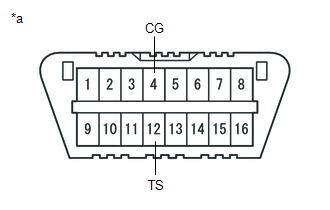
SST: 09843-18040
Text in Illustration
|
*a |
Front view of DLC3 |
(5) Turn the ignition switch to ON.
(6) Check that the ABS warning and SLIP indicator lights come on for several seconds and then blink in Test Mode.
HINT:
If the ABS warning and SLIP indicator lights do not blink, inspect the TS and CG terminal circuit and ABS warning and SLIP indicator light circuits.
|
Trouble Area |
See Procedure |
|---|---|
|
TS and CG terminal circuit |
|
|
ABS warning light circuit (Remains on) |
|
|
ABS warning light circuit (Does not come on) |
|
|
SLIP indicator light circuit (Remains on) |
|
|
SLIP indicator light circuit (Does not come on) |
|
(7) Check the ABS sensors.
HINT:
Check that the ABS warning light is blinking in the Test Mode blinking pattern before performing the ABS sensor check.
(b) Acceleration Sensor Check
(1) Keep the vehicle stationary on a level surface for 1 second or more.
HINT:
The acceleration sensor check can be performed with the master cylinder pressure sensor check below.
(c) Lost Booster Pressure Judgement Check and Master Cylinder Pressure Sensor Zero Point Calibration
NOTICE:
Perform a check in the lost booster pressure state (vacuum in the booster is depressurized).
(1) Turn the ignition switch to ON.
(2) Check that the brake warning light comes on when depressing the brake pedal with a force greater than 59 N (6 kgf, 13.2 lbf) for 1 second or more. (The lost booster pressure state is judged as normal.)
(3) Start the engine while depressing the brake pedal with a force greater than 59 N (6 kgf, 13.2 lbf) for 1 second or more.
(4) Check that the brake warning light goes off when quickly releasing the brake pedal. (The lost booster pressure state is judged as normal.)
(5) Leave the vehicle for 1 second or more. (Master cylinder pressure sensor zero point calibration)
NOTICE:
- If depressing the brake pedal slowly or repeatedly, the master cylinder pressure sensor zero point calibration is not performed normally.
- If the lost booster pressure judgement check results are not normal, then the master cylinder pressure sensor check cannot be performed.
- If rechecking after the engine has started, end Test Mode, enter Test Mode again, and release vacuum in the booster by pumping the brake pedal prior to rechecking.
(d) Master Cylinder Pressure Sensor Check
(1) Leave the vehicle in a stationary condition and release the brake pedal for 1 second or more, then quickly and continuously depress the brake pedal with a force greater than 98 N (10 kgf, 22.0 lbf) for 1 second.
(2) Check that the ABS warning light stays on for 3 seconds.
HINT:
- Confirm that the ABS warning light comes on.
- While the ABS warning light is illuminated, continue to depress the brake pedal with a force of 98 N (10 kgf, 22.0 lbf) or more.
- The ABS warning light comes on for 3 seconds every time the brake pedal operation above is performed.
(e) Speed Sensor Check
(1) Drive the vehicle straight-ahead.
Accelerate the vehicle to a speed of 45 km/h (28 mph) or more for several seconds.
(2) Check that the ABS warning light goes off.
HINT:
- The sensor check may not be completed if wheelspin occurs.
- The ABS warning light blinks when the sensor check has been completed and the brake pedal is depressed.
- The ABS warning light comes on immediately if a malfunction is detected during the speed sensor check.
(3) Stop the vehicle.
NOTICE:
- Before performing the speed sensor check, complete the acceleration sensor and master cylinder pressure sensor checks.
- The speed sensor check may not be completed if the speed sensor check is started while turning the steering wheel or spinning the wheels.
- After the ABS warning light goes off, if the vehicle speed exceeds 80 km/h (50 mph), a sensor check code will be stored again. Decelerate or stop the vehicle before the speed reaches 80 km/h (50 mph).
- If the sensor check has not been completed, the ABS warning light will blink while driving and the ABS will not operate.
HINT:
When the sensor check has been completed, the ABS warning light turns off while driving and blinks in the Test Mode pattern while the vehicle is stationary.
(f) VSC OFF Switch Check
(1) Press the VSC OFF switch.
(2) Check that the VSC OFF indicator light comes on.
(3) Press the VSC OFF switch again.
(g) End of Sensor Check
(1) If the sensor check is completed, the ABS warning light blinks (Test Mode) when the vehicle is stopped and goes off while the vehicle is being driven.
NOTICE:
- When the speed sensor, and master cylinder pressure sensor checks are completed, the sensor check is completed.
- If the sensor check has not been completed, the ABS warning light will blink while driving and the ABS will not operate.
(h) Read Sensor Check DTCs
(1) Using SST, connect terminals TC and CG of the DLC3.
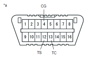
SST: 09843-18040
Text in Illustration
|
*a |
Front view of DLC3 |
(2) Count the number of blinks of the ABS warning light and SLIP indicator lights.
HINT:
- When the system is operating correctly, each light will blink continuously in a pattern of 0.25 seconds on, then 0.25 seconds off.
- When one DTC is output, each light will output the same code at 4 second intervals. (For example, Code 21 would be output as 2 flashes, a 1.5 second pause, and then 1 flash).
- When 2 or more DTCs are output, each light will output a different code at 2.5 second intervals, and when all codes have been output, there will be a 4 second pause and the sequence will repeat.
- When multiple codes are set, they are output in order starting with the lowest DTC number.
- See the list of DTCs (See procedure "A").
NOTICE:
- If only DTCs other than Test Mode sensor check DTCs are displayed, repair the malfunctions and clear the DTCs.
- If Test Mode sensor check DTCs and other DTCs are displayed or if only Test Mode sensor check DTCs are displayed, repair the malfunctions, clear the DTCs, and perform Test Mode inspection again.
(3) After performing the check, disconnect SST from terminals TS and CG, and TC and CG of the DLC3 and turn the ignition switch off.
(4) Turn the ignition switch to ON.
HINT:
- If the ignition switch is not turned to ON after SST is removed from the DLC3, the previous Test Mode will continue.
- If the ignition switch is turned to ON with terminals TS and CG connected, the previous Test Mode will continue.
(i) Sensor Check DTCs
ABS Sensor
|
DTC Code |
Detection Item |
Trouble Area |
|---|---|---|
|
71 |
Low Output Signal of Front Speed Sensor RH |
|
|
72 |
Low Output Signal of Front Speed Sensor LH |
|
|
73 |
Low Output Signal of Rear Speed Sensor RH |
|
|
74 |
Low Output Signal of Rear Speed Sensor LH |
|
|
75 |
Abnormal Change in Output Signal of Front Speed Sensor RH |
Speed sensor rotor |
|
76 |
Abnormal Change in Output Signal of Front Speed Sensor LH |
Speed sensor rotor |
|
77 |
Abnormal Change in Output Signal of Rear Speed Sensor RH |
Speed sensor rotor |
|
78 |
Abnormal Change in Output Signal of Rear Speed Sensor LH |
Speed sensor rotor |
|
79 |
Acceleration Sensor Output Voltage Malfunction |
|
|
81 |
Master Cylinder Pressure Sensor Output Malfunction |
|
|
88*1 |
Initialization Incomplete |
|
- *1: w/ VDIM
HINT:
The codes in this table are output only in Test Mode (signal check).
|
|
|