| Last Modified: 08-28-2024 | 6.11:8.1.0 | Doc ID: RM100000000VIV5 |
| Model Year Start: 2016 | Model: Sienna | Prod Date Range: [12/2015 - 11/2017] |
| Title: BRAKE CONTROL / DYNAMIC CONTROL SYSTEMS: VEHICLE STABILITY CONTROL SYSTEM: TC and CG Terminal Circuit; 2016 - 2017 MY Sienna [12/2015 - 11/2017] | ||
|
TC and CG Terminal Circuit |
DESCRIPTION
Connecting terminals TC and CG of the DLC3 causes the ECU to display the DTC by blinking the ABS warning light and SLIP indicator light.
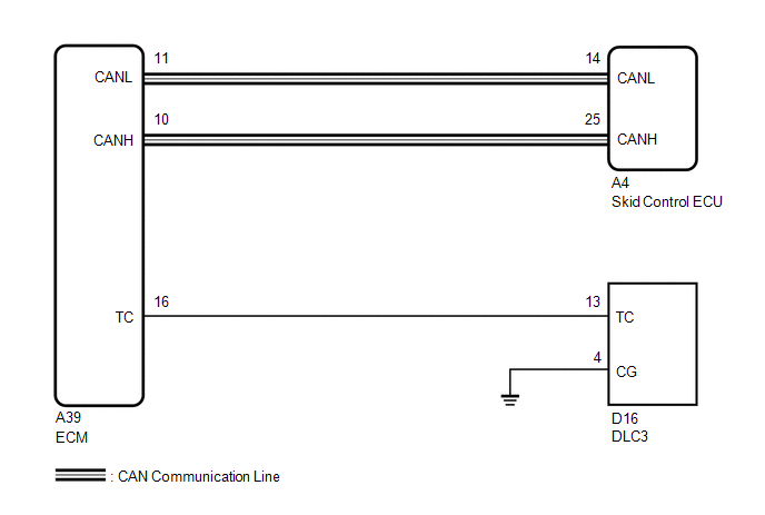
WIRING DIAGRAM
HINT:
When the warning lights continue to blink, a ground short in the wiring of terminal TC of the DLC3 or an internal ground short in one or more ECUs is suspected.
CAUTION / NOTICE / HINT
NOTICE:
When replacing the brake actuator assembly, perform zero point calibration and store system information (See page
![2016 - 2017 MY Sienna [12/2015 - 11/2017]; BRAKE CONTROL / DYNAMIC CONTROL SYSTEMS: VEHICLE STABILITY CONTROL SYSTEM: CALIBRATION](/t3Portal/stylegraphics/info.gif) ).
).
PROCEDURE
|
1. |
CHECK CAN COMMUNICATION SYSTEM |
(a) Check if a CAN communication system DTC is output (See page
).
Result
|
Result |
Proceed to |
|---|---|
|
DTC is not output |
A |
|
DTC is output |
B |
| B |

|
|

|
2. |
INSPECT DLC3 |
|
(a) Turn the ignition switch to ON. |
|
(b) Measure the voltage according to the value(s) in the table below.
Standard Voltage:
|
Tester Connection |
Switch Condition |
Specified Condition |
|---|---|---|
|
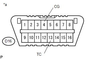
D16-13 (TC) - D16-4 (CG) |
Ignition switch ON |
11 to 14 V |
Text in Illustration
|
*a |
Front view of DLC3 |
Result
|
Result |
Proceed to |
|---|---|
|
NG |
A |
|
OK |
B |
| B |
|
|
|
3. |
CHECK HARNESS AND CONNECTOR (TC of DLC3 - ECM) |
(a) Turn the ignition switch off.
(b) Disconnect the ECM connector.
(c) Measure the resistance according to the value(s) in the table below.
Standard Resistance:
|
Tester Connection |
Condition |
Specified Condition |
|---|---|---|
|
D16-13 (TC) - A39-16 (TC) |
Always |
Below 1 Ω |
|
D16-13 (TC) - Body ground |
Always |
10 kΩ or higher |
| NG |
|
REPAIR OR REPLACE HARNESS OR CONNECTOR |
|
|
4. |
CHECK HARNESS AND CONNECTOR (CG of DLC3 - BODY GROUND) |
|
(a) Measure the resistance according to the value(s) in the table below. Standard Resistance:
Text in Illustration
|
|
| NG |
|
REPAIR OR REPLACE HARNESS OR CONNECTOR |
|
|
5. |
CHECK ECM (TC of DLC3 INPUT) |
|
(a) Turn the ignition switch off. |
|
(b) Reconnect the ECM connector.
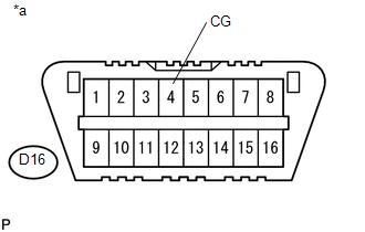
(c) Using SST, connect terminals TC and CG of the DLC3.
SST: 09843-18040
(d) Turn the ignition switch to ON.
(e) Check that the check engine warning light is blinking.
Text in Illustration
|
*a |
Front view of DLC3 |
Result
|
Result |
Proceed to |
|---|---|
|
Check engine warning light is blinking |
A |
|
Check engine warning light is not blinking |
B |
HINT:
If troubleshooting has been carried out according to Problem Symptoms Table, refer back to the table and proceed to the next step before replacing the part (See page
).
| A |
|
| B |
|
REPAIR OR REPLACE WIRE HARNESS OR ECM (TC of ECM CIRCUIT) |
|
|
|