| Last Modified: 08-28-2024 | 6.11:8.1.0 | Doc ID: RM100000000VIRS |
| Model Year Start: 2016 | Model: Sienna | Prod Date Range: [12/2015 - ] |
| Title: AXLE AND DIFFERENTIAL: FRONT AXLE HUB: REMOVAL; 2016 - 2020 MY Sienna [12/2015 - ] | ||
REMOVAL
CAUTION / NOTICE / HINT
HINT:
- Use the same procedure for the RH side and LH side.
- The procedure listed below is for the LH side.
PROCEDURE
1. REMOVE FRONT WHEEL
2. REMOVE FRONT AXLE SHAFT NUT
![2016 MY Sienna [12/2015 - 08/2016]; DRIVE SHAFT / PROPELLER SHAFT: FRONT DRIVE SHAFT ASSEMBLY: REMOVAL+](/t3Portal/stylegraphics/info.gif)
3. SEPARATE FRONT SPEED SENSOR
|
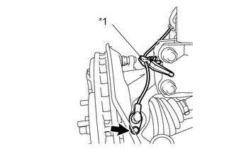
(a) Remove the bolt and resin clamp, and separate the front speed sensor. Text in Illustration
NOTICE:
|
|
4. SEPARATE FRONT DISC BRAKE CALIPER ASSEMBLY
5. REMOVE FRONT DISC
6. SEPARATE TIE ROD ASSEMBLY
7. SEPARATE FRONT LOWER SUSPENSION ARM SUB-ASSEMBLY
|
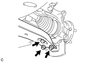
(a) Remove the bolt and 2 nuts, and separate the front lower suspension arm sub-assembly from the front lower ball joint. |
|
8. SEPARATE FRONT DRIVE SHAFT ASSEMBLY
|
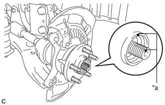
(a) Put matchmarks on the front drive shaft assembly and front axle hub sub-assembly. Text in Illustration
|
|
|
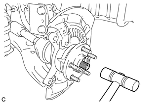
(b) Using a plastic hammer, separate the front drive shaft assembly from the front axle assembly. If it is difficult to separate, tap the end of the front drive shaft assembly using a brass bar and a hammer. NOTICE: Be careful not to damage the drive shaft boot and speed sensor rotor. |
|
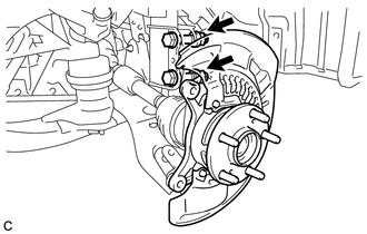
9. REMOVE FRONT AXLE ASSEMBLY
|
(a) Remove the 2 bolts, 2 nuts and front axle assembly. NOTICE:
|
|
10. REMOVE FRONT NO. 1 WHEEL BEARING DUST DEFLECTOR
|
(a) Using a screwdriver with its tip wrapped in protective tape, remove the front No. 1 wheel bearing dust deflector. Text in Illustration
NOTICE: Be careful not to damage the steering knuckle. |
|

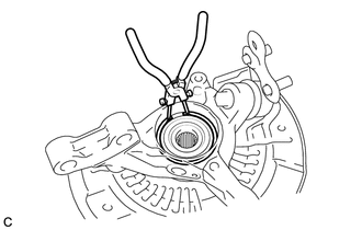
11. REMOVE FRONT AXLE HUB HOLE SNAP RING
|
(a) Using snap ring pliers, remove the front axle hub hole snap ring. |
|
12. REMOVE FRONT AXLE HUB SUB-ASSEMBLY
|
(a) Secure the front axle assembly between aluminum plates in a vise. NOTICE: Do not overtighten the vise. |
|
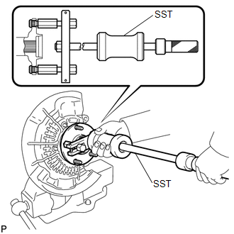
(b) Using SST, remove the front axle hub sub-assembly.
SST: 09520-00031
|
(c) Using SST and a press, remove the front axle hub bearing inner race (outside) from the front axle hub sub-assembly. SST: 09555-55010 SST: 09950-60010 09951-00430 SST: 09950-70010 09951-07100 NOTICE: Be careful not to drop the front axle hub sub-assembly. |
|
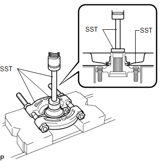
13. REMOVE FRONT AXLE HUB BEARING
|
(a) Place the front axle hub bearing inner race (outside) on the front axle hub bearing. |
|
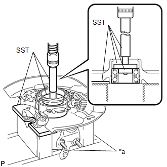
(b) Using SST, V-blocks and a press, remove the front axle hub bearing from the steering knuckle.
If the steering knuckle cannot be kept level using SST, stabilize the steering knuckle using a washer or an equivalent tool.
Text in Illustration
|
*a |
V-block |
SST: 09527-21011
SST: 09950-60010
09951-00440
09952-06010
SST: 09950-60020
09951-00750
SST: 09950-70010
09951-07100
NOTICE:
Keep the steering knuckle level.
|
|
|