| Last Modified: 08-28-2024 | 6.11:8.1.0 | Doc ID: RM100000000VIOS |
| Model Year Start: 2016 | Model: Sienna | Prod Date Range: [12/2015 - 08/2016] |
| Title: U660F (AUTOMATIC TRANSMISSION / TRANSAXLE): SHIFT LEVER: ADJUSTMENT; 2016 MY Sienna [12/2015 - 08/2016] | ||
ADJUSTMENT
PROCEDURE
1. ADJUST SHIFT LEVER POSITION
(a) Move the shift lever to N.
|
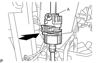
(b) Disconnect the transmission control switch connector and shift lock control ECU connector. Text in Illustration
|
|
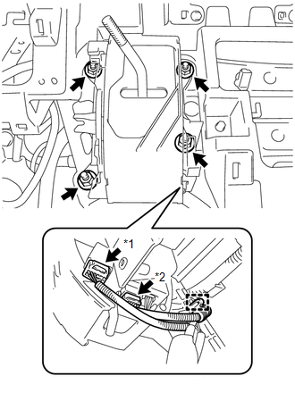
(c) Disengage the clamp to separate the wire harness from the shift lever assembly.
(d) Remove the 4 nuts and shift lever assembly from the instrument panel reinforcement.
|
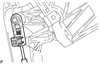
(e) Disconnect the end of the transmission control cable assembly from the shift lever assembly. |
|
|
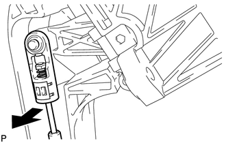
(f) Using a screwdriver, pull out the stopper of the transmission control cable assembly. NOTICE: Do not remove the stopper. If the stopper is removed, reinstall it to its original position. |
|
|
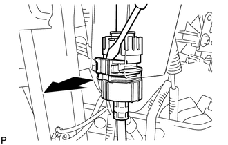
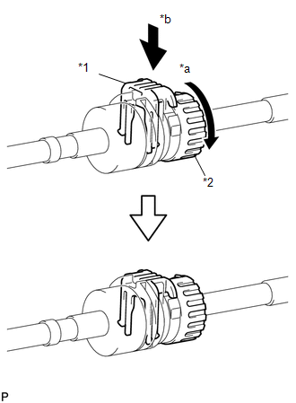
(g) Rotate the nut of the transmission control cable assembly counterclockwise approximately 270° and while holding the nut in that position, separate the cable outer of the transmission control cable assembly from the shift lever retainer. |
|
|
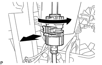
(h) Rotate the nut of the transmission control cable assembly counterclockwise approximately 270° and while holding the nut in that position, press in the stopper until it makes 2 "click" sounds. Text in Illustration
|
|
|
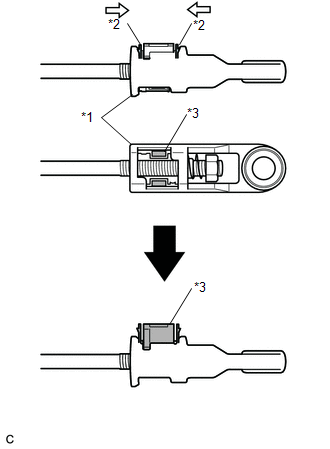
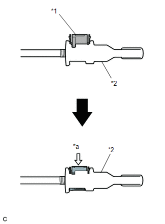
(i) Push the lock piece up from the back side of the adjuster case while pinching the claws on the lock piece. Text in Illustration
|
|
(j) Check that the park/neutral position switch and the shift lever are in N position.
|
(k) Install the cable outer of the transmission control cable assembly to the shift lever retainer, check that the position of the spring is the same as A shown in the illustration, and press in the stopper. HINT: If the stopper cannot be pressed in, slightly rotate the nut clockwise and then press in the stopper. |
|
|
(l) Connect the end of the transmission control cable assembly to the shift lever assembly. Text in Illustration
NOTICE: Check that the lock piece is pulled up. |
|
(m) Install the shift lever assembly to the instrument panel reinforcement with the 4 nuts.
Torque:
12 N·m {122 kgf·cm, 9 ft·lbf}
(n) Engage the clamp to install the wire harness to the shift lever assembly.
(o) Connect the shift lock control ECU connector and transmission control switch connector.
|
(p) Press in and lock the lock piece to the adjuster case. Text in Illustration
NOTICE:
|
|
2. INSPECT SHIFT LEVER POSITION
![2016 MY Sienna [12/2015 - 08/2016]; U660F (AUTOMATIC TRANSMISSION / TRANSAXLE): SHIFT LEVER: ON-VEHICLE INSPECTION+](/t3Portal/stylegraphics/info.gif)
|
|
|