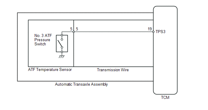
- ATF temperature sensor assembly (No. 3 ATF pressure switch)
- Transmission wire
- TCM
| Last Modified: 08-28-2024 | 6.11:8.1.0 | Doc ID: RM100000000VINI |
| Model Year Start: 2016 | Model: Sienna | Prod Date Range: [12/2015 - 08/2016] |
| Title: U660F (AUTOMATIC TRANSMISSION / TRANSAXLE): AUTOMATIC TRANSAXLE SYSTEM: P0989,P0990; Transmission Fluid Pressure Sensor / Switch "E" Circuit Low; 2016 MY Sienna [12/2015 - 08/2016] | ||
|
DTC |
P0989 |
Transmission Fluid Pressure Sensor / Switch "E" Circuit Low |
|
DTC |
P0990 |
Transmission Fluid Pressure Sensor / Switch "E" Circuit High |
DESCRIPTION
No. 3 ATF pressure switch is installed in the lock-up solenoid automatic transmission fluid (ATF) output passage and is used to detect a malfunction in the lock-up solenoid.
|
DTC No. |
DTC Detection Condition |
Trouble Area |
|---|---|---|
|
P0989 |
No. 3 ATF pressure switch is OFF when lock-up occurs in response to a lock-up request (2 trip detection logic). |
|
|
P0990 |
When both of the following are detected (2 trip detection logic):
|
MONITOR DESCRIPTION
The TCM illuminates the MIL and stores the DTC when the TCM detects that the ATF pressure switch is OFF with the lock-up solenoid ON or when the TCM detects that the ATF pressure switch is ON with the lock-up solenoid OFF.
MONITOR STRATEGY
|
Related DTCs |
P0989: No. 3 ATF pressure switch OFF malfunction P0990: No. 3 ATF pressure switch ON malfunction |
|
Required sensors/Components |
No. 3 ATF pressure switch |
|
Frequency of operation |
Continuous |
|
Duration |
P0989: 1.8 seconds P0990 (a): 1.2 seconds P0990 (b): 0.6 seconds |
|
MIL operation |
2 driving cycles |
|
Sequence of operation |
None |
TYPICAL ENABLING CONDITIONS
ALL:
|
The monitor will run whenever this DTC is not present. (Not circuit malfunction) |
P0712, P0713 (ATF temperature sensor circuit (TFT sensor)) P0115, P0117, P0118 (ECT sensor circuit) P0715, P0717 (Input speed sensor (NT) circuit) P0791, P0793 (Output speed sensor (NC) circuit) P0748 (Shift solenoid valve SL1 circuit) P0778 (Shift solenoid valve SL2 circuit) P0798 (Shift solenoid valve SL3 circuit) P2810 (Shift solenoid valve SL4 circuit) P2759 (Shift solenoid valve SLU circuit) P2769, P2770 (Shift solenoid valve SL circuit) P0327, P0328, P0332, P0333 (KCS sensor circuit) P0120, P0121, P0122, P0123, P0220, P0222, P0223, P0604, P0606, P060A, P060B, P060D, P060E, P0657, P1607, P2102, P2103, P2111, P2112, P2118, P2119, P2135 ((ETCS) Electronic throttle control system) U0100 (CAN communication system) |
|
Engine coolant temperature |
40°C (104°F) or more |
|
Spark advance from Max. retard timing by KCS control |
0°CA or more |
|
Transmission range |
D |
|
TFT (Transmission fluid temperature) |
-10°C (14°F) or more |
|
TFT (Transmission fluid temperature) sensor circuit |
No circuit malfunction |
|
ECT (Engine coolant temperature) sensor circuit |
No circuit malfunction |
|
Input speed sensor (NT) circuit |
No circuit malfunction |
|
Output speed sensor (NC) circuit |
No circuit malfunction |
|
Shift solenoid valve SL1 circuit |
No circuit malfunction |
|
Shift solenoid valve SL2 circuit |
No circuit malfunction |
|
Shift solenoid valve SL3 circuit |
No circuit malfunction |
|
Shift solenoid valve SL4 circuit |
No circuit malfunction |
|
Shift solenoid valve SLU circuit |
No circuit malfunction |
|
Shift solenoid valve SL circuit |
No circuit malfunction |
|
KCS (Knock control sensor circuit) |
No circuit malfunction |
|
(ETCS) Electronic throttle control system |
Not system down |
|
CAN communication system |
Not system down |
|
Engine |
Starting |
|
TCM selected gear |
Not 1st |
|
Vehicle speed |
25 km/h (15.5 mph) or more |
|
Input speed (NT) / Output speed (NO) with 1st |
3.304 to 7.724 |
|
Input speed (NT) / Output speed (NO) with 2nd |
1.901 to 2.340 |
|
Input speed (NT) / Output speed (NO) with 3rd |
1.399 to 1.649 |
|
Input speed (NT) / Output speed (NO) with 4th |
0.998 to 1.138 |
|
Input speed (NT) / Output speed (NO) with 5th |
0.705 to 0.836 |
|
Input speed (NT) / Output speed (NO) with 6th |
0.568 to 0.695 |
P0989:
|
TCM lock-up command |
ON (SLU pressure: 513 kPa (5.2 kgf/ cm2, 74 psi) or more |
|
Engine speed (NE) - Input speed (NT) |
Less than 35 rpm |
|
Throttle valve opening angle |
7% or more |
|
Vehicle speed |
Less than 120 km/h (74.6 mph) |
|
Shift solenoid valve SLU |
Not ON malfunction |
P0990:
|
TCM indicated pressure valve of SLU |
0 kPa |
|
TCM lock-up command |
OFF (SLU pressure: less than 4 kPa (0.04 kgf/ cm2, 0.6 psi) |
|
Shift solenoid valve SLU |
Not malfunction |
|
Shift solenoid valve SL |
Not OFF malfunction |
TYPICAL MALFUNCTION THRESHOLDS
P0989:
|
No. 3 transmission fluid pressure switch |
OFF |
P0990:
|
Following conditions are met |
(a) and (b) |
|
(a) l Engine speed (NE) - Input speed (NT) l |
35 rpm or more |
|
(b) No. 3 transmission fluid pressure switch |
ON |
WIRING DIAGRAM
CAUTION / NOTICE / HINT
NOTICE:
Perform the universal trip to clear permanent DTCs (See page
![2016 MY Sienna [12/2015 - 08/2016]; U660F (AUTOMATIC TRANSMISSION / TRANSAXLE): AUTOMATIC TRANSAXLE SYSTEM: DTC CHECK / CLEAR](/t3Portal/stylegraphics/info.gif) ).
).
PROCEDURE
|
1. |
CHECK OTHER DTC OUTPUT (IN ADDITION TO DTC P0989 OR P0990) |
(a) Connect the Techstream to the DLC3.
(b) Turn the ignition switch to ON.
(c) Turn the Techstream on.
(d) Enter the following menus: Powertrain / ECT / Trouble Codes.
(e) Read the DTCs using the Techstream.
Result
|
Result |
Proceed to |
|---|---|
|
Only P0990 is output |
A |
|
Only P0989 is output |
B |
|
P0989 or P0990 and other DTCs are output |
C |
HINT:
If a solenoid is stuck OFF, DTCs for several solenoids including the malfunctioning solenoid will be detected.
| B |

|
| C |
|
|

|
2. |
INSPECT TRANSMISSION WIRE (NO. 3 ATF PRESSURE SWITCH) |
|
(a) Remove the TCM. |
|
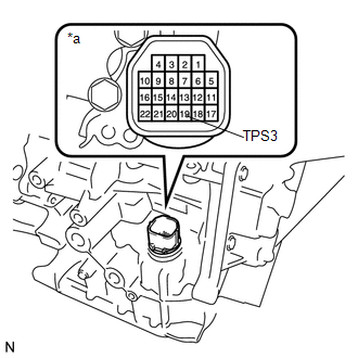
(b) Measure the resistance according to the value(s) in the table below.
Standard Resistance:
|
Tester Connection |
Condition |
Specified Condition |
|---|---|---|
|
19 (TPS3) - Body ground (Valve body assembly) or other terminals |
Always |
10 kΩ or higher |
Text in Illustration
|
*a |
Component without harness connected (Transmission Wire) |
| OK |
|
|
|
3. |
INSPECT ATF TEMPERATURE SENSOR ASSEMBLY (NO. 3 ATF PRESSURE SWITCH) |
(a) Remove the oil strainer assembly.
|
(b) Disconnect the connector from the ATF temperature sensor assembly. |
|
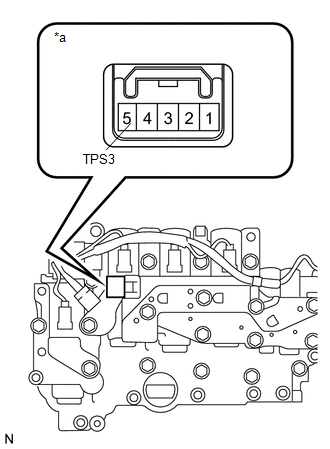
(c) Measure the resistance according to the value(s) in the table below.
Standard Resistance:
|
Tester Connection |
Condition |
Specified Condition |
|---|---|---|
|
5 (TPS3) - Body ground (Valve body assembly) or other terminals |
Always |
10 kΩ or higher |
Text in Illustration
|
*a |
Component without harness connected (ATF Temperature Sensor) |
| OK |
|
| NG |
|
|
4. |
INSPECT TRANSMISSION WIRE |
(a) Remove the oil strainer assembly.
|
(b) Remove the TCM. |
|
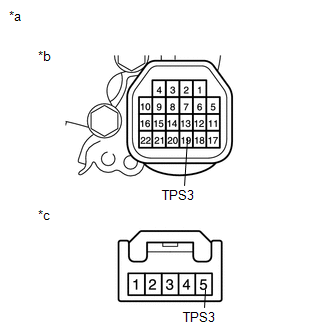
(c) Disconnect the connector from the ATF temperature sensor assembly.
(d) Measure the resistance according to the value(s) in the table below.
Standard Resistance:
|
Tester Connection |
Condition |
Specified Condition |
|---|---|---|
|
19 (TPS3) - 5 (TPS3) |
Always |
Below 1 Ω |
|
5 (TPS3) - Body ground (Valve body assembly) or other terminals |
Always |
10 kΩ or higher |
Text in Illustration
|
*a |
Component without harness connected (Transmission Wire) |
|
*b |
TCM Side |
|
*c |
ATF Temperature Sensor Side |
| NG |
|
|
|
5. |
REPLACE ATF TEMPERATURE SENSOR ASSEMBLY |
(a) Replace ATF temperature sensor (See page
).
|
|
6. |
CHECK DTC OUTPUT |
(a) Connect the Techstream to the DLC3.
(b) Start the engine and turn the Techstream on.
(c) Enter the following menus: Powertrain / ECT / Trouble Codes / Clear.
HINT:
Write down the currently output DTCs before clearing them.
(d) Perform the monitor drive pattern (See page
).
(e) Enter the following menus: Powertrain / ECT / Trouble Codes.
(f) Read the DTCs using the Techstream.
Result
|
Result |
Proceed to |
|---|---|
|
DTC not output |
A |
|
Only P0989 is output |
B |
| A |
|
END |
| B |
|
|
|
|