- Ignition switch ON
- Battery voltage is 10.5 V or more
- No communication between the ECM and TCM
| Last Modified: 08-28-2024 | 6.11:8.1.0 | Doc ID: RM100000000VINE |
| Model Year Start: 2016 | Model: Sienna | Prod Date Range: [12/2015 - 08/2016] |
| Title: U660F (AUTOMATIC TRANSMISSION / TRANSAXLE): AUTOMATIC TRANSAXLE SYSTEM: U0100; Lost Communication with ECM / PCM "A"; 2016 MY Sienna [12/2015 - 08/2016] | ||
|
DTC |
U0100 |
Lost Communication with ECM / PCM "A" |
DESCRIPTION
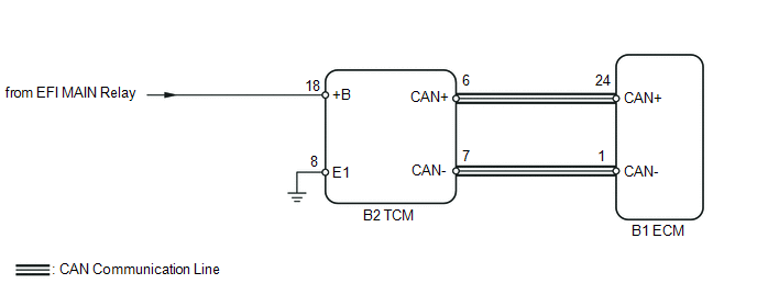
The engine control unit communicates with the TCM using the Controller Area Network (CAN).
If there is a problem in this communication, the TCM sets a DTC.
|
DTC No. |
DTC Detection Condition |
Trouble Area |
|---|---|---|
|
U0100 |
Following conditions are met for 1.25 seconds (1 trip detection logic): |
|
MONITOR STRATEGY
|
Related DTCs |
U0100: Verify communication |
|
Required Sensors/Components (Main) |
TCM |
|
Required Sensors/Components (Related) |
- |
|
Frequency of Operation |
Continuous |
|
Duration |
1.25 seconds |
|
MIL Operation |
Immediate |
|
Sequence of Operation |
None |
TYPICAL ENABLING CONDITIONS
|
Monitor runs whenever following DTCs not present |
None |
|
Battery Voltage |
10.5 V or more |
|
Ignition Switch |
ON |
|
Starter |
OFF |
TYPICAL MALFUNCTION THRESHOLDS
|
Communication between TCM and ECM |
No communication |
WIRING DIAGRAM

CAUTION / NOTICE / HINT
NOTICE:
Perform the universal trip to clear permanent DTCs (See page
![2016 MY Sienna [12/2015 - 08/2016]; U660F (AUTOMATIC TRANSMISSION / TRANSAXLE): AUTOMATIC TRANSAXLE SYSTEM: DTC CHECK / CLEAR](/t3Portal/stylegraphics/info.gif) ).
).
HINT:
- Refer to inspection procedure for CAN communication system.
- If the CAN communication malfunctions, the TCM cannot receive the current data from the ECM. In this case, the freeze frame data output from the TCM has not been updated, so the data will not be useful for the inspection. However, reading the Data List as the first step in troubleshooting is effective to find malfunctions.
-
The malfunction area can be checked using the Bus Check function on the Techstream (See page
![2016 MY Sienna [12/2015 - 08/2016]; NETWORKING: CAN COMMUNICATION SYSTEM: DIAGNOSIS SYSTEM](/t3Portal/stylegraphics/info.gif) ).
).
PROCEDURE
|
1. |
CHECK ECU TERMINAL VOLTAGE (+B AND E1 TERMINALS) |
|
(a) Disconnect the TCM connector. |
|
(b) Turn the ignition switch to ON.
(c) Measure the voltage according to the value(s) in the table below.
Standard Voltage:
|
Tester Connection |
Switch Condition |
Specified Condition |
|---|---|---|
|
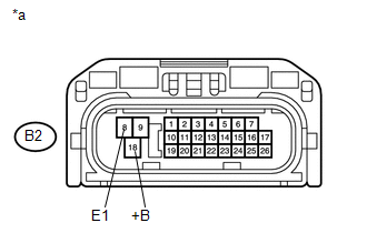
B2-18 (+B) - B2-8 (E1) |
Ignition switch ON |
11 to 14 V |
(d) Turn the ignition switch off.
(e) Measure the resistance according to the value(s) in the table below.
Standard Resistance:
|
Tester Connection |
Condition |
Specified Condition |
|---|---|---|
|
B2-8 (E1) - Body ground |
Always |
Below 1 Ω |
Text in Illustration
|
*a |
Front view of wire harness connector (to TCM) |
| NG |

|
REPAIR OR REPLACE HARNESS OR CONNECTOR |
|
|
2. |
CHECK HARNESS AND CONNECTOR (TCM - ECM) |
(a) Disconnect the TCM connector.
(b) Disconnect the ECM connector.
(c) Measure the resistance according to the value(s) in the table below.
Standard Resistance:
|
Tester Connection |
Condition |
Specified Condition |
|---|---|---|
|
B2-6 (CAN+) - B1-24 (CAN+) |
Always |
Below 1 Ω |
|
B2-7 (CAN-) - B1-1 (CAN-) |
Always |
Below 1 Ω |
|
B2-6 (CAN+) or B1-24 (CAN+) - Body ground or other terminals |
Always |
1 MΩ or higher |
|
B2-7 (CAN-) or B1-1 (CAN-) - Body ground or other terminals |
Always |
1 MΩ or higher |
| NG |

|
REPAIR OR REPLACE HARNESS OR CONNECTOR |
|
|
3. |
REPLACE TCM |
(a) Replace the TCM (See page
![2016 MY Sienna [12/2015 - 08/2016]; U660F (AUTOMATIC TRANSMISSION / TRANSAXLE): TCM: REMOVAL](/t3Portal/stylegraphics/info.gif) ).
).
HINT:
Replace the TCM with a TCM from a normally functioning vehicle of the same model.
|
|
4. |
CHECK DTC OUTPUT |
(a) Connect the Techstream to the DLC3.
(b) Start the engine.
(c) Turn the Techstream on.
(d) Enter the following menus: Powertrain / ECT / Trouble Codes.
(e) Read the DTCs using the Techstream.
Result
|
Result |
Proceed to |
|---|---|
|
DTC not output |
A |
|
U0100 is output |
B |
| A |

|
END |
| B |

|
|
|
|

