| Last Modified: 08-28-2024 | 6.11:8.1.0 | Doc ID: RM100000000VIKL |
| Model Year Start: 2016 | Model: Sienna | Prod Date Range: [12/2015 - 08/2016] |
| Title: U660E (AUTOMATIC TRANSMISSION / TRANSAXLE): AUTOMATIC TRANSAXLE SYSTEM: Transmission Control Switch Circuit; 2016 MY Sienna [12/2015 - 08/2016] | ||
|
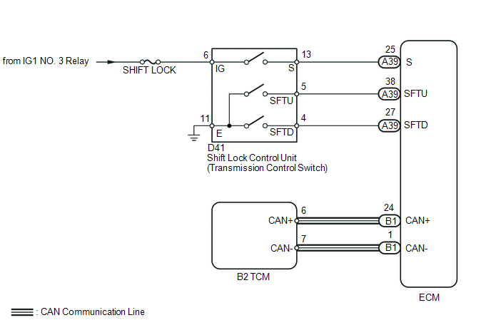
Transmission Control Switch Circuit |
DESCRIPTION
When the shift lever is in S and it is moved toward "-" or "+", it is possible to select different shift ranges (1st through 6th ranges).
Moving the shift lever toward "+" increases the shift range by one, and moving the shift lever toward "-" decreases the shift range by one.
WIRING DIAGRAM
CAUTION / NOTICE / HINT
NOTICE:
Inspect the fuses for circuits related to this system before performing the following inspection procedure.
PROCEDURE
|
1. |
CHECK HARNESS AND CONNECTOR (BATTERY - TRANSMISSION CONTROL SWITCH) |
|
(a) Disconnect the transmission control switch connector of shift lock control unit. |
|
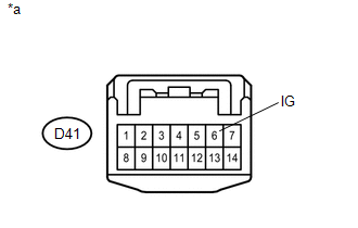
(b) Turn the ignition switch to ON.
(c) Measure the voltage according to the value(s) in the table below.
Standard Voltage:
|
Tester Connection |
Switch Condition |
Specified Condition |
|---|---|---|
|
D41-6 (IG) - Body ground |
Ignition switch ON |
11 to 14 V |
|
Ignition switch off |
Below 1 V |
Text in Illustration
|
*a |
Front view of wire harness connector (to Transmission Control Switch) |
| NG |

|
REPAIR OR REPLACE HARNESS OR CONNECTOR |
|

|
2. |
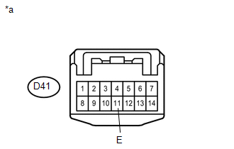
CHECK HARNESS AND CONNECTOR (TRANSMISSION CONTROL SWITCH - BODY GROUND) |
|
(a) Measure the resistance according to the value(s) in the table below. Standard Resistance:
Text in Illustration
|
|
| NG |
|
REPAIR OR REPLACE HARNESS OR CONNECTOR |
|
|
3. |
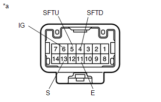
INSPECT SHIFT LOCK CONTROL UNIT (TRANSMISSION CONTROL SWITCH) |
|
(a) Measure the resistance according to the value(s) in the table below. Standard Resistance:
Text in Illustration
|
|
| NG |
|
REPLACE SHIFT LOCK CONTROL UNIT (TRANSMISSION CONTROL SWITCH) |
|
|
4. |
CHECK HARNESS AND CONNECTOR (TRANSMISSION CONTROL SWITCH - ECM) |
(a) Disconnect the ECM connector.
(b) Measure the resistance according to the value(s) in the table below.
Standard Resistance:
|
Tester Connection |
Condition |
Specified Condition |
|---|---|---|
|
D41-4 (SFTD) - A39-27 (SFTD) |
Always |
Below 1 Ω |
|
D41-5 (SFTU) - A39-38 (SFTU) |
Always |
Below 1 Ω |
|
D41-13 (S) - A39-25 (S) |
Always |
Below 1 Ω |
|
D41-4 (SFTD) - Body ground |
Always |
10 kΩ or higher |
|
D41-5 (SFTU) - Body ground |
Always |
10 kΩ or higher |
|
D41-13 (S) - Body ground |
Always |
10 kΩ or higher |
| OK |
|
PROCEED TO NEXT SUSPECTED AREA SHOWN IN PROBLEM SYMPTOMS TABLE |
| NG |
|
REPAIR OR REPLACE HARNESS OR CONNECTOR |
|
|
|