| Last Modified: 08-28-2024 | 6.11:8.1.0 | Doc ID: RM100000000VIK6 |
| Model Year Start: 2016 | Model: Sienna | Prod Date Range: [12/2015 - 08/2016] |
| Title: U660E (AUTOMATIC TRANSMISSION / TRANSAXLE): AUTOMATIC TRANSAXLE ASSEMBLY(When Not Using the Engine Support Bridge): INSTALLATION; 2016 MY Sienna [12/2015 - 08/2016] | ||
INSTALLATION
PROCEDURE
1. INSTALL SPEEDOMETER DRIVEN HOLE COVER SUB-ASSEMBLY
(a) Apply a light coat of ATF to a new O-ring and install it to the speedometer driven hole cover sub-assembly.
NOTICE:
Do not twist the O-ring.
(b) Install the speedometer driven hole cover sub-assembly to the automatic transaxle assembly with the bolt.
Torque:
5.5 N·m {56 kgf·cm, 49 in·lbf}
NOTICE:
Make sure that the O-ring is not damaged or does not jump out of position during installation.
2. INSTALL NO. 1 TRANSMISSION CONTROL CABLE BRACKET
(a) Install the No. 1 transmission control cable bracket to the automatic transaxle assembly with the 2 bolts.
Torque:
12 N·m {122 kgf·cm, 9 ft·lbf}
3. INSTALL WIRE HARNESS CLAMP BRACKET
(a) Install the 5 wire harness clamp brackets to the automatic transaxle assembly with the 5 bolts.
Torque:
8.4 N·m {85 kgf·cm, 74 in·lbf}
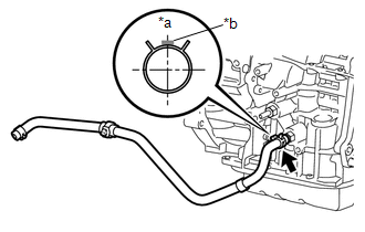
4. INSTALL NO. 1 OIL COOLER INLET HOSE
|
(a) Install the No. 1 oil cooler inlet hose to the automatic transaxle assembly with the hose clip as shown in the illustration. Text in Illustration
|
|
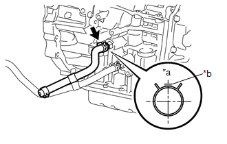
5. INSTALL NO. 1 OIL COOLER OUTLET HOSE
|
(a) Install the No. 1 oil cooler outlet hose to the automatic transaxle assembly with the hose clip as shown in the illustration. Text in Illustration
|
|
6. INSTALL OIL COOLER TUBE CLAMP
(a) Engage the 2 clamps to install the oil cooler tube clamp to the No. 1 oil cooler inlet hose and No. 1 oil cooler outlet hose.
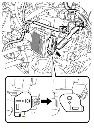
7. INSTALL TCM
|
(a) Temporarily install the TCM to the automatic transaxle assembly with the 2 bolts. |
|
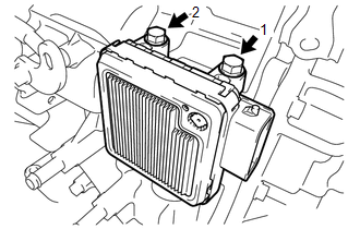
(b) Tighten the 2 bolts in the order shown in the illustration.
Torque:
11 N·m {115 kgf·cm, 8 ft·lbf}
8. INSTALL FRONT ENGINE MOUNTING BRACKET
(a) Clean and degrease the stud bolt installation hole in the automatic transaxle assembly.
(b) Using an E8 "TORX" socket wrench, install a new stud bolt to the automatic transaxle assembly.
Torque:
21 N·m {214 kgf·cm, 15 ft·lbf}
(c) Install the front engine mounting bracket to the automatic transaxle assembly with the 2 bolts and nut.
Torque:
64 N·m {653 kgf·cm, 47 ft·lbf}
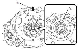
9. INSTALL TORQUE CONVERTER ASSEMBLY
|
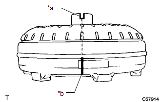
(a) Set the key at the top of the front oil pump drive gear and put a matchmark on the transaxle housing. Text in Illustration
|
|
|
(b) Place a matchmark on the torque converter assembly so that the position of its groove is clearly indicated. Text in Illustration
|
|
|
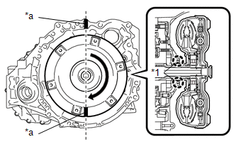
(c) Align the matchmark on the transaxle housing with the one on the torque converter assembly and engage the splines of the input shaft with the turbine runner splines. Text in Illustration
NOTICE:
|
|

|
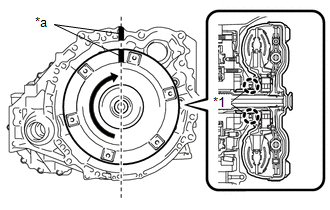
(d) Rotate the torque converter assembly approximately 180° and engage the splines of the stator shaft with the stator assembly. Text in Illustration
NOTICE:
|
|
|
(e) Rotate the torque converter assembly approximately 180° again, align the matchmark on the torque converter assembly with the one on the transaxle housing and insert the groove of the torque converter assembly into the key of the front oil pump drive gear. Text in Illustration
NOTICE:
|
|
(f) Clean the drive plate and torque converter assembly setting bolt holes.
|
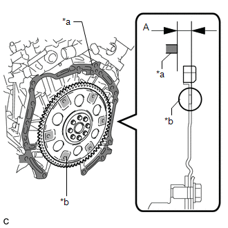
(g) Using a vernier caliper and straightedge, measure dimension A between the automatic transaxle assembly contact surface of the engine assembly*a and the torque converter assembly contact surface of the drive plate*b. Text in Illustration
|
|
|
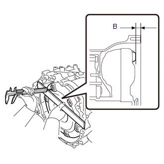
(h) Using a vernier caliper and straightedge, measure dimension B shown in the illustration and check that dimension B is more than dimension A, which was measured in the previous step. Standard distance: B = A + 1 mm (0.0394 in.) or more NOTICE:
|
|
10. INSTALL AUTOMATIC TRANSAXLE ASSEMBLY
(a) Apply clutch spline grease to the surface of the crankshaft that contacts the torque converter assembly centerpiece.
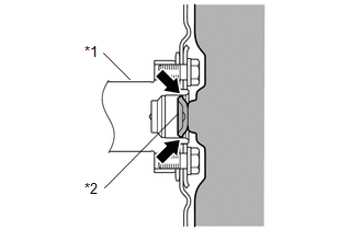
Text in Illustration
|
*1 |
Crankshaft |
|
*2 |
Torque Converter Assembly Centerpiece |

|
Clutch Spline Grease |
Grease:
Toyota Genuine Clutch Spline Grease or equivalent
Maximum grease amount:
Approximately 1 g (0.0353 oz.)
|
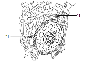
(b) Confirm that the 2 knock pins are installed on the engine assembly and are not damaged. Text in Illustration
|
|
|
(c) Clean and degrease the bolt C and installation hole in the automatic transaxle assembly. |
|
(d) Apply adhesive to 2 or 3 threads on the end of the bolt C.
Adhesive:
Toyota Genuine Adhesive 1324, Three Bond 1324 or equivalent
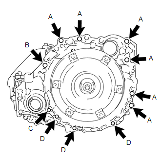
(e) Maintain the engine assembly and automatic transaxle assembly in a horizontal position, align the knock pins with each hole in the automatic transaxle assembly and install the automatic transaxle assembly to the engine assembly with the 11 bolts.
Torque:
Bolt A :
64 N·m {653 kgf·cm, 47 ft·lbf}
Bolt B :
64 N·m {653 kgf·cm, 47 ft·lbf}
Bolt C :
46 N·m {469 kgf·cm, 34 ft·lbf}
Bolt D :
43 N·m {439 kgf·cm, 32 ft·lbf}
Bolt Length:
|
Bolt |
Length mm (in.) |
|---|---|
|
A |
55 (2.17) |
|
B |
50 (1.97) |
|
C |
41 (1.61) |
|
D |
33 (1.30) |
NOTICE:
- Make sure that the wire harness or similar items are not pinched between the contact surfaces.
- Do not forcibly pry on the automatic transaxle assembly.
- When mounting the automatic transaxle assembly to the engine assembly, make sure to securely fit the knock pins into the knock holes.
- Check that the torque converter assembly rotates.
- When tightening the bolts, be sure that the contact surfaces of the engine assembly and automatic transaxle assembly are in close contact with one another.
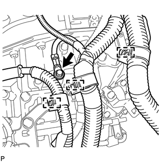
11. CONNECT ENGINE WIRE
|
(a) Engage the 4 clamps to install the engine wire to the automatic transaxle assembly. Text in Illustration
|
|
(b) Connect the connector to the TCM.
(c) Turn the lock lever and secure the connector with the lock lever.
|
(d) Engage the 3 clamps to install the engine wire to the automatic transaxle assembly. |
|
(e) Install the ground wire to the automatic transaxle assembly with the bolt.
Torque:
19 N·m {195 kgf·cm, 14 ft·lbf}
|
(f) Engage the clamp to install the engine wire to the automatic transaxle assembly. |
|
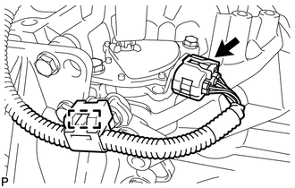
(g) Connect the park/neutral position switch connector.
12. INSTALL BREATHER PLUG HOSE
(a) Engage the clamp to install the breather plug hose to the hose clamp.
13. INSTALL MANIFOLD STAY
![2016 MY Sienna [12/2015 - 08/2016]; 2GR-FE INTAKE / EXHAUST: EXHAUST MANIFOLD: INSTALLATION+](/t3Portal/stylegraphics/info.gif)
14. INSTALL STARTER ASSEMBLY
15. INSTALL ENGINE ASSEMBLY WITH TRANSAXLE
(See page
)
16. CHECK AUTOMATIC TRANSAXLE SYSTEM
NOTICE:
If automatic transaxle parts have been replaced, refer to Parts Replacement Compensation Table to determine if any additional operations are necessary (See page
).
|
|
|