- Communication circuit
- Millimeter wave radar sensor
- Driving support ECU
| Last Modified: 08-28-2024 | 6.11:8.1.0 | Doc ID: RM100000000VII5 |
| Model Year Start: 2016 | Model: Sienna | Prod Date Range: [12/2015 - 08/2016] |
| Title: CRUISE CONTROL: DYNAMIC RADAR CRUISE CONTROL SYSTEM: U1102; Lost Communication with Radar Sensor; 2016 MY Sienna [12/2015 - 08/2016] | ||
|
DTC |
U1102 |
Lost Communication with Radar Sensor |
DESCRIPTION
The millimeter wave radar sensor and driving support ECU transmit the data for general vehicle control and diagnosis function along the CAN communication line. The driving support ECU determines the curve radius information based on signals from the steering wheel and yaw rate and acceleration sensor. The driving support ECU transmits the current vehicle speed and curve radius information to the millimeter wave radar sensor.
|
DTC No. |
DTC Detection Condition |
Trouble Area |
|---|---|---|
|
U1102 |
The ECM detects a communication error signal (from the driving support control ECU to the millimeter wave radar sensor) for 0.15 seconds or more while the dynamic radar cruise control is in operation |
|
WIRING DIAGRAM
Refer to wiring diagram for DTC U0235 (See page
![2016 MY Sienna [12/2015 - 08/2016]; CRUISE CONTROL: DYNAMIC RADAR CRUISE CONTROL SYSTEM: U0235; Lost Communication with Cruise Control Front Distance Range Sensor+](/t3Portal/stylegraphics/info.gif) ).
).
CAUTION / NOTICE / HINT
NOTICE:
-
When the millimeter wave radar sensor is replaced with a new one, adjustment of the radar sensor beam axis must be performed (See page
).
- Inspect the fuses for circuits related to this system before performing the following inspection procedure.
PROCEDURE
|
1. |
CHECK CAN COMMUNICATION SYSTEM |
(a) Select "CAN Bus Check" from the "System Selection Menu" on the Techstream.
(b) Select "Communication Malfunction Check" from the "CAN Bus Check" screen, and then select "OK".
OK:
CAN communication is normal.
| NG |

|
|

|
2. |
CHECK HARNESS AND CONNECTOR (DRIVING SUPPORT ECU - MILLIMETER WAVE RADAR SENSOR) |
(a) Disconnect the A44 driving support ECU connector.
(b) Disconnect the A36 millimeter wave radar sensor connector.
(c) Measure the resistance according to the value(s) in the table below.
Standard Resistance:
|
Tester Connection |
Condition |
Specified Condition |
|---|---|---|
|
A44-40 (CA1P) - A36-4 (CA1P) |
Always |
Below 1 Ω |
|
A44-18 (CA1N) - A36-3 (CA1N) |
Always |
Below 1 Ω |
|
A44-40 (CA1P) or A36-4 (CA1P) - Body ground |
Always |
10 kΩ or higher |
|
A44-18 (CA1N) or A36-3 (CA1N) - Body ground |
Always |
10 kΩ or higher |
| NG |
|
REPAIR OR REPLACE HARNESS AND CONNECTOR |
|
|
3. |
CHECK HARNESS AND CONNECTOR (DRIVING SUPPORT ECU - POWER SOURCE) |
|
(a) Disconnect the driving support ECU connector. |
|
(b) Measure the voltage according to the value(s) in the table below.
Standard Voltage:
|
Tester Connection |
Switch Condition |
Specified Condition |
|---|---|---|
|
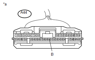
A44-30 (B) - Body ground |
Ignition switch ON |
11 to 14 V |
Text in Illustration
|
*a |
Front view of wire harness connector (to Driving Support ECU) |
| NG |
|
REPAIR OR REPLACE HARNESS OR CONNECTOR |
|
|
4. |
CHECK HARNESS AND CONNECTOR (DRIVING SUPPORT ECU - BODY GROUND) |
|
(a) Disconnect the driving support ECU connector. |
|
(b) Measure the resistance according to the value(s) in the table below.
Standard Resistance:
|
Tester Connection |
Condition |
Specified Condition |
|---|---|---|
|
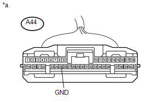
A44-25 (GND) - Body ground |
Always |
Below 1 Ω |
Text in Illustration
|
*a |
Front view of wire harness connector (to Driving Support ECU) |
(c) Reconnect the driving support ECU connector.
| NG |
|
REPAIR OR REPLACE HARNESS OR CONNECTOR |
|
|
5. |
CHECK HARNESS AND CONNECTOR (MILLIMETER WAVE RADAR - SENSOR POWER SOURCE) |
|
(a) Disconnect the millimeter wave radar sensor connector. |
|
(b) Measure the voltage according to the value(s) in the table below.
Standard Voltage:
|
Tester Connection |
Switch Condition |
Specified Condition |
|---|---|---|
|
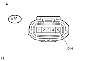
A36-5 (IGB) - Body ground |
Ignition switch ON |
11 to 14 V |
|
A36-5 (IGB) - Body ground |
Ignition switch OFF |
Below 1 V |
Text in Illustration
|
*a |
Front view of wire harness connector (to Millimeter Wave Radar Sensor) |
| NG |
|
REPAIR OR REPLACE HARNESS OR CONNECTOR |
|
|
6. |
CHECK HARNESS AND CONNECTOR (MILLIMETER WAVE RADAR SENSOR - BODY GROUND) |
|
(a) Disconnect the millimeter wave radar sensor connector. |
|
(b) Measure the resistance according to the value(s) in the table below.
Standard Resistance:
|
Tester Connection |
Condition |
Specified Condition |
|---|---|---|
|
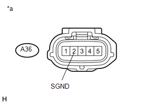
A36-2 (SGND) - Body ground |
Always |
Below 1 Ω |
Text in Illustration
|
*a |
Front view of wire harness connector (to Millimeter Wave Radar Sensor) |
| NG |
|
REPAIR OR REPLACE HARNESS OR CONNECTOR |
|
|
7. |
REPLACE MILLIMETER WAVE RADAR SENSOR |
(a) Replace the millimeter wave radar sensor with a new one (See page
).
(b) Perform millimeter wave radar sensor adjustment (See page
).
|
|
8. |
CHECK DTC OUTPUT |
(a) Clear the DTCs (See page
).
(b) Perform the following to make sure that the DTC detection conditions are met.
HINT:
If the detection conditions are not met, the malfunction cannot be detected.
(1) Drive the vehicle at a speed of 50 km/h (30 mph) or more.
(2) Turn the cruise control main switch on.
(3) Push the -SET switch to activate the cruise control.
(c) Check for DTCs (See page
).
Result
|
Result |
Proceed to |
|---|---|
|
DTC is not output |
A |
|
DTC U1102 is output |
B |
| A |
|
END |
| B |
|
|
|
|