| Last Modified: 08-28-2024 | 6.11:8.1.0 | Doc ID: RM100000000VIH5 |
| Model Year Start: 2016 | Model: Sienna | Prod Date Range: [12/2015 - 08/2016] |
| Title: CRUISE CONTROL: CRUISE CONTROL SYSTEM: Cruise Control Switch Circuit; 2016 MY Sienna [12/2015 - 08/2016] | ||
|
Cruise Control Switch Circuit |
DESCRIPTION
The cruise control main switch operates 7 functions: SET, - (COAST), TAP-DOWN, RES (RESUME), + (ACCEL), TAP-UP, and CANCEL. The SET, TAP-DOWN, and - (COAST) functions, and the RES (RESUME), TAP-UP, and + (ACCEL) functions are operated with the same switch. The cruise control main switch is an automatic return type switch which turns on only while operating it in the direction of each arrow and turns off after releasing it. The internal contact point of the cruise control main switch is turned on with the switch operation. Then the ECM reads the voltage value that has been changed by the switch operation to control SET, - (COAST), RES (RESUME), + (ACCEL), and CANCEL.
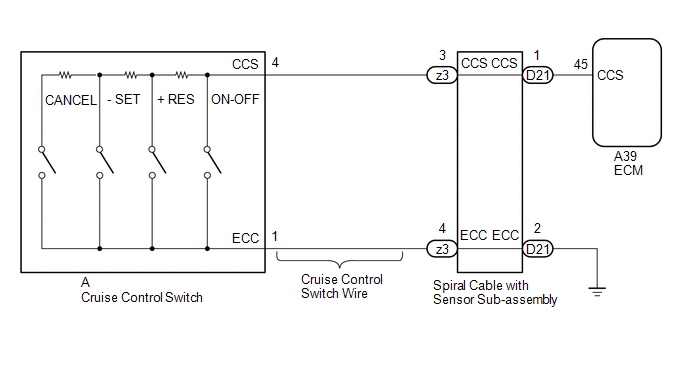
WIRING DIAGRAM
CAUTION / NOTICE / HINT
NOTICE:
The vehicle is equipped with a Supplemental Restraint System (SRS) which includes components such as airbags. Before servicing (including removal or installation of parts), be sure to read the precaution for Supplemental Restraint System (See page
![2016 - 2020 MY Sienna [12/2015 - ]; SUPPLEMENTAL RESTRAINT SYSTEMS: AIRBAG SYSTEM: PRECAUTION](/t3Portal/stylegraphics/info.gif) ).
).
PROCEDURE
|
1. |
READ VALUE USING TECHSTREAM |
(a) Connect the Techstream to the DLC3.
(b) Turn the ignition switch to ON.
(c) Turn the Techstream on.
(d) Enter the following menus: Powertrain / Cruise Control / Data List.
(e) Read the Data List according to the display on the Techstream.
Cruise Control
|
Tester Display |
Measurement Item/Range |
Normal Condition |
Diagnostic Note |
|---|---|---|---|
|
Main SW M-CPU |
Main switch signal (Main CPU)/ON or OFF |
ON: Main switch depressed OFF: Main switch released |
- |
|
Cancel Switch |
CANCEL switch signal/ON or OFF |
ON: While switch is being operated OFF: Switch not operated |
- |
|
SET/COAST Switch |
SET/COAST switch signal/ON or OFF |
ON: While switch is being operated OFF: Switch not operated |
- |
|
RES/ACC Switch |
RES/ACC switch signal/ON or OFF |
ON: While switch is being operated OFF: Switch not operated |
- |
OK:
When the cruise control main switch is operated, the display changes as shown above.
| OK |

|
PROCEED TO NEXT SUSPECTED AREA SHOWN IN PROBLEM SYMPTOMS TABLE |
|

|
2. |
INSPECT CRUISE CONTROL MAIN SWITCH |
(a) Remove the cruise control main switch (See page
).
(b) Inspect the cruise control main switch (See page
).
| NG |
|
|
|
3. |
INSPECT CRUISE CONTROL SWITCH WIRE |
|
(a) Disconnect the cruise control switch wire connector from the spiral cable with sensor sub-assembly and cruise control main switch. |
|
(b) Measure the resistance according to the value(s) in the table below.
Standard Resistance:
|
Tester Connection |
Condition |
Specified Condition |
|---|---|---|
|
A-4 (CCS) - z3-3 (CCS) |
Always |
Below 1 Ω |
|
A-1 (ECC) - z3-4 (ECC) |
Always |
Below 1 Ω |
|
A-4 (CCS) or z3-3 (CCS) - Body Ground |
Always |
10 kΩ or higher |
|
A-1 (ECC) or z3-4 (ECC) - Body Ground |
Always |
10 kΩ or higher |
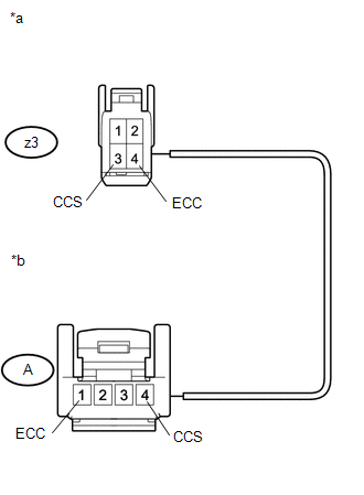
Text in Illustration
|
*a |
Front view of wire harness connector (to Spiral Cable with Sensor Sub-assembly) |
|
*b |
Front view of wire harness connector (to Cruise Control Main Switch) |
| NG |
|
REPAIR OR REPLACE HARNESS OR CONNECTOR |
|
|
4. |
INSPECT SPIRAL CABLE WITH SENSOR SUB-ASSEMBLY |
(a) Remove the spiral cable with sensor sub-assembly (See page
).
(b) Inspect the spiral cable with sensor sub-assembly (See page
).
| NG |
|
|
|
5. |
CHECK HARNESS AND CONNECTOR (SPIRAL CABLE WITH SENSOR SUB-ASSEMBLY - ECM AND BODY GROUND) |
(a) Disconnect the D21 spiral cable with sensor sub-assembly connector.
(b) Disconnect the A39 ECM connector.
(c) Measure the resistance according to the value(s) in the table below.
Standard Resistance:
|
Tester Connection |
Condition |
Specified Condition |
|---|---|---|
|
D21-1 (CCS) - A39-45 (CCS) |
Always |
Below 1 Ω |
|
D21-1 (CCS) or A39-45 (CCS) - Body ground |
Always |
10 kΩ or higher |
|
D21-2 (ECC) - Body ground |
Always |
Below 1 Ω |
| OK |
|
| NG |
|
REPAIR OR REPLACE HARNESS OR CONNECTOR |
|
|
|