| Last Modified: 08-28-2024 | 6.11:8.1.0 | Doc ID: RM100000000VIGM |
| Model Year Start: 2016 | Model: Sienna | Prod Date Range: [12/2015 - 08/2016] |
| Title: 2GR-FE STARTING: STARTER: INSPECTION; 2016 MY Sienna [12/2015 - 08/2016] | ||
INSPECTION
PROCEDURE
1. INSPECT STARTER ASSEMBLY
NOTICE:
These tests must be performed within 3 to 5 seconds to avoid burning out the coil.
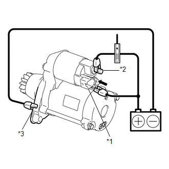
(a) Perform a pull-in test.
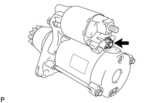
(1) Remove the nut and disconnect the lead wire from terminal C.
|
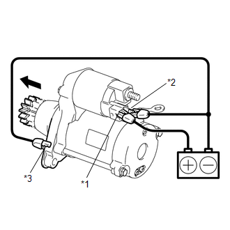
(2) Connect the battery to the magnetic switch as shown in the illustration. Check that the clutch pinion gear is extended. Text in Illustration
If the clutch pinion gear does not move, replace the magnetic switch assembly. |
|
|
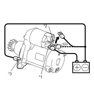
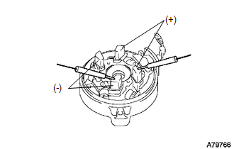
(b) Perform a holding test. (1) Disconnect the negative (-) lead from terminal C. Check that the clutch pinion gear remains extended. Text in Illustration
If the clutch pinion gear returns inward, replace the magnetic switch assembly. |
|
|
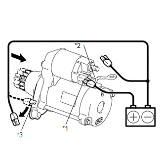
(c) Inspect the clutch pinion gear return. (1) Disconnect the negative (-) lead from the starter body. Check that the clutch pinion gear returns. Text in Illustration
If the clutch pinion gear does not return inward, replace the magnetic switch assembly. |
|
(d) Perform a no-load performance test.
(1) Connect the lead wire to terminal C with the nut. Make sure that the lead is not grounded.
Torque:
10 N·m {102 kgf·cm, 7 ft·lbf}
(2) Clamp the starter in a vise.
NOTICE:
Do not clamp the vise too tightly.
|
(3) Connect the battery and an ammeter to the starter as shown in the illustration. NOTICE: Do not allow any lead to get caught as the pinion gear rotates. Text in Illustration
|
|
(4) Check that the starter rotates smoothly and steadily with the pinion gear extended.
(5) Measure the current according to the value(s) in the table below.
Standard Current:
|
Tester Connection |
Condition |
Specified Condition |
|---|---|---|
|
Battery positive terminal - Terminal 30 |
11.5 V |
90 A or less |
If the result is not as specified, replace the starter assembly.
2. INSPECT MAGNETIC SWITCH ASSEMBLY
|
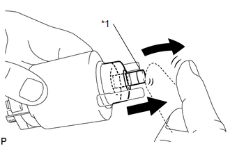
(a) Check the plunger. (1) Push in the plunger and check that it returns quickly to its original position. Text in Illustration
If necessary, replace the magnetic switch assembly. |
|
|
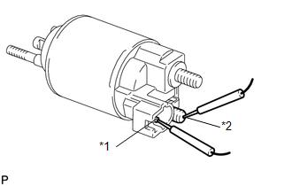
(b) Check if the pull-in coil for an open circuit. (1) Measure the resistance according to the value(s) in the table below. Text in Illustration
Standard Resistance:
If the result is not as specified, replace the magnetic switch assembly. |
|
|
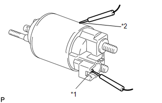
(c) Check the holding coil for an open circuit. (1) Measure the resistance according to the value(s) in the table below. Text in Illustration
Standard Resistance:
If the result is not as specified, replace the magnetic switch assembly. |
|
3. INSPECT STARTER ARMATURE ASSEMBLY
(a) Check the commutator for contamination and burns on its surface.
If the surface is dirty or burnt, correct it with sandpaper (No. 400) or a lathe.
|
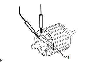
(b) Check the commutator. (1) Measure the resistance according to the value(s) in the table below. Text in Illustration
Standard Resistance:
If the result is not as specified, replace the starter armature assembly. |
|
|
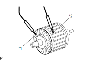
(c) Check the commutator. (1) Measure the resistance according to the value(s) in the table below. Text in Illustration
Standard Resistance:
If the result is not as specified, replace the starter armature assembly. |
|
|
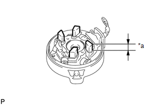
(d) Using a vernier caliper, measure the commutator length. Text in Illustration
Standard length: 3.1 to 3.8 mm (0.122 to 0.149 in.) If the length is greater than the maximum, replace the starter armature assembly. |
|
4. INSPECT STARTER COMMUTATOR END FRAME ASSEMBLY
|
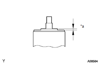
(a) Using a vernier caliper, measure the brush length. Text in Illustration
Standard length: 4.0 to 9.0 mm (0.158 to 0.354 in.) If the length is less than the minimum, replace the starter commutator end frame assembly. |
|
|
(b) Check the brush insulation. (1) Measure the resistance according to the value(s) in the table below. Standard Resistance:
If the result is not as specified, replace the starter commutator end frame assembly. |
|
5. INSPECT STARTER CLUTCH SUB-ASSEMBLY
|
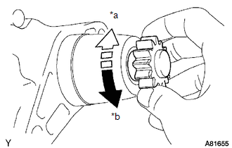
(a) Rotate the clutch pinion gear counterclockwise and check that it turns freely. Try to rotate the clutch pinion gear clockwise and check that it locks. Text in Illustration
If necessary, replace the repair service starter kit. |
|
|
|
|